Concrete Relief Shelve Walls - An Innovative Method of Earth Retention
Relief shelve walls are a unique concept that use only conventional construction materials like PCC / RCC / steel reinforcements, and work on a completely different fundamental to resist the lateral load caused due to soil. Information on the various dimensions of the relief-shelve’ system is presented in this paper to encourage designers, planners, and structural engineers to understand and use this technique in their projects and avail the benefits.
Er. Vivek Abhyankar, Founder, SGAWings Civil Engineering Consultant and Advisor (OPC), Mumbai
In a conventional gravity type wall, the wall resists the lateral load caused by a massive soil block behind, whereas in the relief-shelve system the overall soil block itself is split into smaller shelves/wedges/blocks with the help of ‘relief shelve slab’, resulting in substantial reduction of the lateral pressure acting on the wall. Hence, the overall size of components (stem thickness, width of footing etc) required for the wall are significantly reduced. This can also result in substantial saving in the material quantity, construction time, and overall cost, as well as reducing the risks involved.
In conventional retaining walls, after several years, due to either overloading, or material creep, or even design or construction faults, if the wall starts leaning or bulging, then a ‘progressive collapse’ may eventually occur. But in the case of the ‘relief-shelve’ system, if the wall starts leaning, then the factor of safety increases slightly due to the deformed shape, and the collapse gets delayed (ductile failure/converging behavior).
Due to these unique actions, this wall is suitable for places where the required height of the wall is high (10m to 30m or more) but the available width of land is restricted (as on hilly roads). However, certain cautionary points have to be remembered by the designers, planners, and site engineers so that they can thoroughly understand and use this technique in their ongoing/upcoming projects and avail the maximum benefits for the project, company, and for the nation at large.
Introduction
While working on civil engineering projects, we rarely encounter a flat earth surface; the land is often undulating, uneven, wavy, hilly, or near a valley, a gorge; or with ponds, puddles, rivers, embankments; or touching an existing road, railway line or a building. Especially in long length project stretches like roads, railways, runways etc, the level differences of land are routine. At such locations we use ‘earth retaining walls’ to maintain the level difference between two sides of soil by laterally holding the soil/fill on the higher side.
Civil engineering professionals are generally aware about various conventional earth retention systems such as Stone masonry walls, PCC block walls, Timber shoring, Reinforced concrete retaining walls (flat surface, counterfort type, buttress type, arch type), Steel pile shoring (cantilever/anchored/strutted), contiguous pile wall, secant pile wall, diaphragm / slurry walls, Reinforced Earth (RE) panels, gabion walls, crib walls, and hollow box returns. Each of these types consume different materials viz. steel, concrete, stone, timber, geotextile, but often work on similar fundamentals to resist the lateral pressure caused by the soil; and each of them have certain merits and limitations. These systems can be used ‘in isolation’ or ‘in combination’ with other system/s or technologies (for example, with ground anchors, soil nails, or two materials together (a hybrid system) depending on site conditions. Each of these types and the resulting combinations have certain benefits and limitations.
The retained soil has a natural tendency to become flatter, and while doing so it exerts enormous lateral pressure on the retaining wall holding or retaining the soil. Hence, we need to apply stability checks against (a) overturning, (b) sliding, and (c) base pressure to the proposed structure of the wall. Due to earth pressure, the wall gets deformed or displaced. When the displacement occurs away from the retained soil mass (easing the soil particles) then it is called ‘active earth condition’. In certain cases, part of wall or whole wall moves towards the soil mass itself; such a case is called ‘passive earth condition’ (where the retained soil mass gets compressed and hence offers a large resistance to wall movements).
Respective coefficients are called as active (ka) or pass (kp) earth pressure coefficients. In certain cases, in spite of the soil mass exerting pressure on structure it doesn’t move (like a buried pipe or a box culvert or an underpass structure), such a case is called as ‘at rest’ condition and the respective coefficient is called as at-rest coefficient ‘k0’. The magnitude of lateral pressures (ka / kp / k0) depends on the (i) type of soil, (ii) surcharge loads, (iii) shape of the walls – height, width, inclination of back (earth face) and base, founding depths, intermediate struts, (iv) water level / pore pressure / and drainage arrangements. Based on combination of these factors two solutions are available, namely– Columb’s solution (CS) and, Rankine’s solution (RS). The difference between magnitude of ka, k0 and kp is graphically explained in a later figure (see Fig.14).
The concept of ‘relief-shelve’ wall was established almost sixty years back in the 1960s. Most of the initial attempts to implement it in real life situation, could not succeed, but certainly gave a lot of information about the behavior of these types of walls. Unfortunately, the overall attempts to implement it in the industry got limited/ignored. In the past ten years or so, in India various attempts were made to implement this technology in real life projects- including a couple of the author’s own works. The lateral earth pressure in the case of conventional and ‘relief-shelve’ wall is shown in Fig.1.
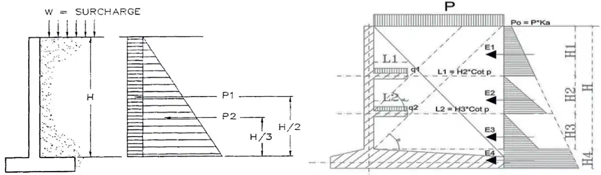 Figure 1: Lateral pressure (a) on conventional cantilever wall (b) on relief shelve system
Brief Review of Conventional Earth Retaining Walls
Before discussing the relief-shelf system, the conventional types of earth retaining walls are briefly described below.
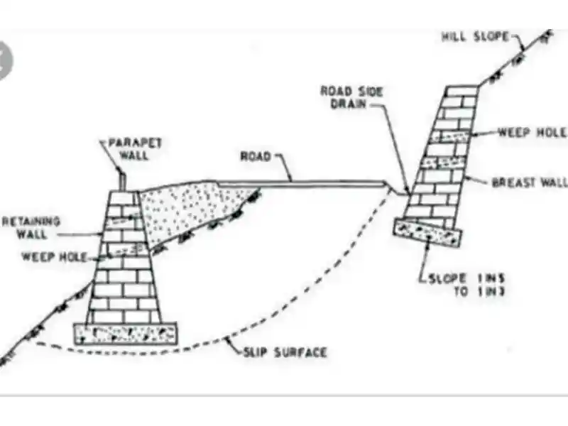 Figure 2: Typical Stone Masonary wall
Stone masonry walls (Fig.2): These are the pioneering type of wall constructions; they are terribly slow to build and consume more construction material as compared to other types (now a days, NHAI launches big projects only for two years duration). They also require skilled workers. Also, the height is restricted as per the safe bearing capacity of soil (SBC) and the type of stone used (UCS). They have longer life (30 to 40 years) which can be extended more with proper maintenance. Some of the Indian forts have walls standing for more than 100 years (Vivek Abhyankar, 2022).
Figure 2: Typical Stone Masonary wall
Stone masonry walls (Fig.2): These are the pioneering type of wall constructions; they are terribly slow to build and consume more construction material as compared to other types (now a days, NHAI launches big projects only for two years duration). They also require skilled workers. Also, the height is restricted as per the safe bearing capacity of soil (SBC) and the type of stone used (UCS). They have longer life (30 to 40 years) which can be extended more with proper maintenance. Some of the Indian forts have walls standing for more than 100 years (Vivek Abhyankar, 2022).
Stone masonry walls are suitable from 0.5 m to 2 m heights. Strong binding mortar and long through / key-stones are required in the construction. For taller walls, engineers use reinforcement rods in place of ‘key-stones’. In the case of non-availability of stones, engineers often use ‘PCC blocks’ for making walls. For drainage and reduction of pore water pressure, weep holes and filter media is recommended. Expansion joints are also given at certain intervals.
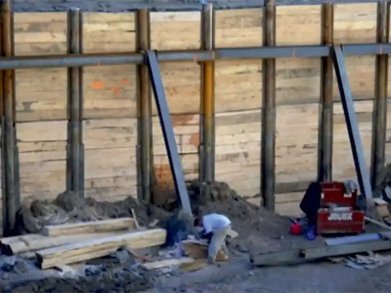 Figure 3: Typical Timber Shoring
Timber shoring wall (Fig.3): They comprise of central H-Shaped steel or a concrete post to engage / lock timber planks in their groove. They are easy and fast to construct; however, they are used for smaller heights up to 3 to 4m (considering the limited flexural capacity of timber planks). For larger heights, a horizontal waler, inclined props with reduced spacing of posts can be used. Sometimes, passive ground anchors are also used to hold the vertical post. These walls have comparatively smaller life (20 years or so) due to which they are preferred for temporary construction works.
Figure 3: Typical Timber Shoring
Timber shoring wall (Fig.3): They comprise of central H-Shaped steel or a concrete post to engage / lock timber planks in their groove. They are easy and fast to construct; however, they are used for smaller heights up to 3 to 4m (considering the limited flexural capacity of timber planks). For larger heights, a horizontal waler, inclined props with reduced spacing of posts can be used. Sometimes, passive ground anchors are also used to hold the vertical post. These walls have comparatively smaller life (20 years or so) due to which they are preferred for temporary construction works.
Reinforced Concrete Wall – Cantilever type: (Fig.4) They are very much preferred due to fast construction. But the base width required is very large like stone masonry wall (gravity type walls). Height is limited to about 5 to 10m. These types of walls can avail the benefit of soil weight on active side by extending the heel slab. They have better monolithic body than the stone masonry.
Sometimes the wall height is less but the intensity of lateral pressure is higher (may be inclination of upper side ground or larger surcharge load on the upper side). In such case, to avoid sliding of the wall, a monolithic vertical extension called as ‘shear-key’ is provided in the base slab.
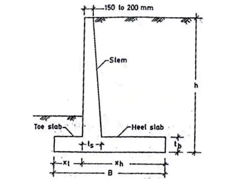 Figure 4: RCC cantilever wall
Due to flexural action in stem, the crack width control becomes important aspect (0.2 mm on soil face and 0.3mm on the open face). At the juction of stem and base slab usualy ‘haunches’ are provided to deal with concentrated stresses and possibility of weak (honeycomb) concrete due to lack of vibrations and congested rebars. In taller RCC walls, safety precautions play a vital role; there are several cases studies of workers getting severly injured due to the callapse of rebar cage from stem portion, during reinforcement tying!
Figure 4: RCC cantilever wall
Due to flexural action in stem, the crack width control becomes important aspect (0.2 mm on soil face and 0.3mm on the open face). At the juction of stem and base slab usualy ‘haunches’ are provided to deal with concentrated stresses and possibility of weak (honeycomb) concrete due to lack of vibrations and congested rebars. In taller RCC walls, safety precautions play a vital role; there are several cases studies of workers getting severly injured due to the callapse of rebar cage from stem portion, during reinforcement tying!
Counterfort / Buttressed wall (Fig.5): When the height of wall increases the thickness of cantilever stem also increases proportionately (due to increase in the bending moment due to lateral soil pressure). In such case, instead of providing flat or a plane rectangular cross-section of stem (in plan), monolithic stiffeners can be cast (which looks like a ‘T-shaped cross section in plan’), these monolithic stiffeners are called ‘counterforts’ or ‘buttresses’ depending on their direction with respect to retained soil fill.
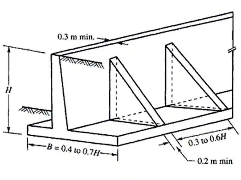 Figure 5: RC counterfort type wall
Steel sheet pile walls (Fig.6): They are quick to install, can sustain larger loads due to inherent strength of steel and the stiffness of bent profile (i.e. form-resistance); also durable for direct exposure to water. They can be constructed in curved shape as well, so suitable for marine structures and cofferdams. But they are extremely costly as compared with other options. They also require a crane and a vibro-hammer for installation. Often best suited for marine construction works and temporary cofferdams. There applicability can be enhanced further (in terms of load capacity, depth, etc.) when used in combination with struts/walers / anchors.
Figure 5: RC counterfort type wall
Steel sheet pile walls (Fig.6): They are quick to install, can sustain larger loads due to inherent strength of steel and the stiffness of bent profile (i.e. form-resistance); also durable for direct exposure to water. They can be constructed in curved shape as well, so suitable for marine structures and cofferdams. But they are extremely costly as compared with other options. They also require a crane and a vibro-hammer for installation. Often best suited for marine construction works and temporary cofferdams. There applicability can be enhanced further (in terms of load capacity, depth, etc.) when used in combination with struts/walers / anchors.
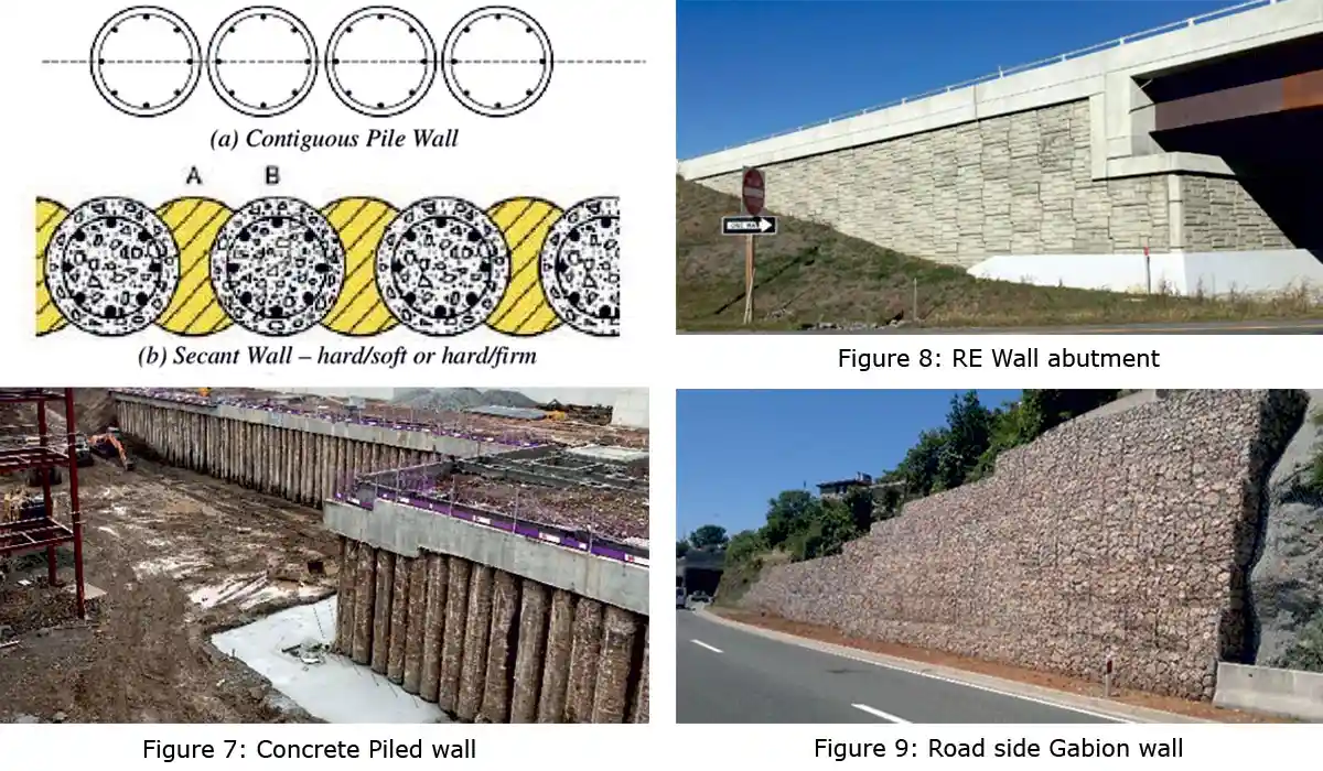
Contiguous (touching piles) & Secant pile wall (Fig.7): These walls comprise of closely driven / touching piles. They are slow to construct as compared to other types, although can sustain larger loads. They are most suited for entry/exists of underground metro stations or deeper cross passages, etc. Due to possible construction inaccuracies (i.e., gaps between piles during driving), contiguous piles are preferred for temporary works than permanent works.
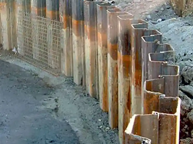 Figure 6: Typical Steel sheet pile wall
Their applicability can be increased for greater depths with the help of lateral supports using multilevel struts and walers on cut side or soil anchors on active soil side. The diaphragm walls are like this but contain larger monolithic rectangular RC panels in place of small circular piles. They are very expensive. Water stop bar are inserted between two diaphragm wall panels to control the seepage of water.
Figure 6: Typical Steel sheet pile wall
Their applicability can be increased for greater depths with the help of lateral supports using multilevel struts and walers on cut side or soil anchors on active soil side. The diaphragm walls are like this but contain larger monolithic rectangular RC panels in place of small circular piles. They are very expensive. Water stop bar are inserted between two diaphragm wall panels to control the seepage of water.
Reinforced earth (RE) type wall (Fig.8): These types of walls look elegant and require sophisticated construction. They are equally costly, and not preferred in case of permanent exposure to water (baring a few exceptions). Slow to construct, preferred for bridge abutments, ramps, approaches, entry exists to airports, etc. They can be constructed up to certain limited heights (say, 10 to 11m); they also require firm ground (better SBC) and engineered backfill as compared to other gravity walls. They utilize the friction between soil and anchors / geotextile buried in the retained soil behind. They require firm drainage arrangement unlike other types where weep holes can be given.
Gabion wall (Fig.9): They are made up from masses of densely packed stone pieces, manually packed in steel wire mesh crates or boxes. They are more environment friendly. Due to the porous nature, they do not require a separate drainage arrangement like weep holes (however geotextile is provided on the backside to arrest wash-out of soil particles). They are suited for permanent as well as temporary works. Faster to construct as compared to RCC or piled walls. No separate cranes or hammers are required; but highly skilled craftsmen are required for packing the stones as the efficiency depends on the packing of stones. As compared to other types of retaining walls they are more flexible; can be used up to about 15m.
Crib Wall (Fig.10): Crib walls are formed from interlocking precast units or timber sleepers (arranged orthogonally in each layer) to form a series of hollow boxes. The boxes are filled with selected granular material to form a retaining wall. They are popularly used in many countries in gardens or even road projects. They are suitable for shall heights from 2m to 7m.
Hollow Box type return / abutment walls: Sometimes, in tall bridge abutments instead of using a single solid plate type RCC wall, a hollow box type RCC structural arrangement is used; it comprises of two or more flat vertical walls [right from footing raft till Finished Road level (FRL) supported with a beam column grid work. They have a larger moment of inertia as compared to solid section of wall; thus, there is a material saving but land / space required is larger.
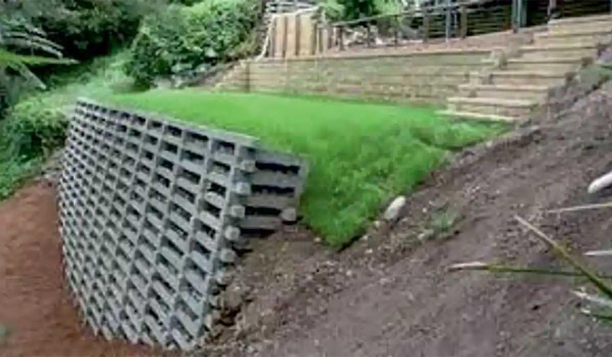 Figure 10: Crib wall
Hybrid Systems: From above solutions it can be understood that from 0.5m up to 15m height, several solutions are available for soil retention. For larger height of retention, often designers prefer a stepped fill, but it consumes much larger land; stability of such large embankments could also be of concern. Sometimes (rarely), engineers are forced to use hybrid type of wall for further larger heights (say 20m) which contains a combination of any two options described above e.g., (i) Gabion wall on the top of RCC wall or (ii) an RE wall over piled wall etc. (as per the site conditions). Approval of such walls and to ensure their longevity is a challenging issue. Hybrid walls are useful for larger heights but may not be economical; also, they include the limitations of both the systems, together for the said project. Also, it could be a potential risk in high seismic zones. In such situations, the relief-shelve wall is a most suitable option at highly affordable price.
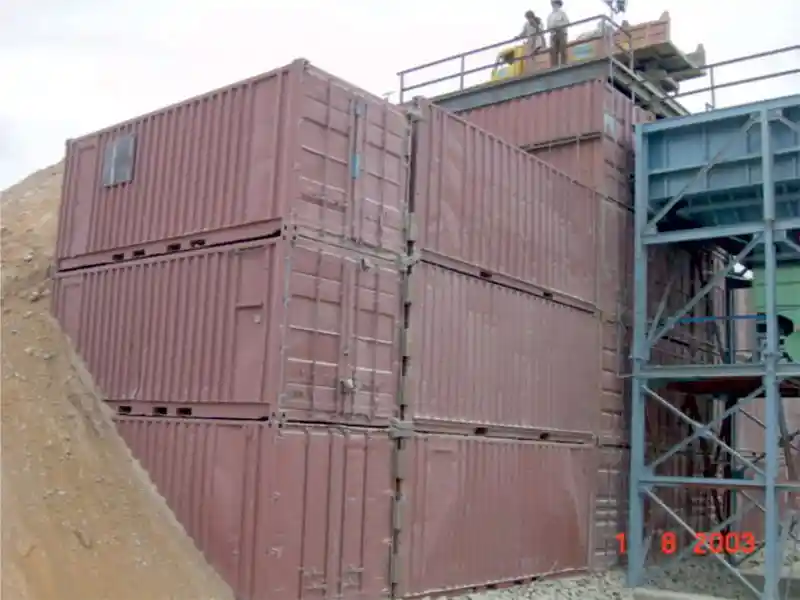 Figure 11: Retaining wall using Steel Containers (Ref. HCC Year 2003)
Some Creative Solutions
Figure 11: Retaining wall using Steel Containers (Ref. HCC Year 2003)
Some Creative Solutions
Engineers are so creative, that they keep exploring available materials and structural forms in the nature and life in general, for the benefit of society (in terms of - cost, construction time, ease, efficiency, aesthetics, and longevity). One such crude, yet creative application can be seen in Fig. 11, where the author had used empty steel cargo containers to retain the soil embankment in a crushing plant of one road project in India. The wall performed very well but it is suitable only for limited life (say, 3 to 5 years). Of course, it also requires availability of old empty scrap steel containers (otherwise would prove to be very costly). Even aesthetically they are not very pleasant; also consume huge space as compared to conventional walls.
Use of Geofoam Behind Retaining Walls
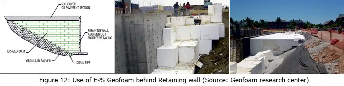
From the discussion till now, it may be clear that the large soil masses/blocks/embankments behind the earth retaining walls cause a huge lateral force on the structure of the wall. Controlling, restricting or reducing these lateral pressures is the sole aim in the earth retaining technology. As stated earlier, engineers always find innovative ways to solve engineering problems. ‘Geofoam’ is yet another such solution. Geofoam is expanded polystyrene or extruded polystyrene manufactured into large lightweight blocks. These blocks vary in size but are often found to be of size 2 m × 0.75 m × 0.75 m. The primary function of geofoam is to provide a lightweight void fill below a highway, bridge approach, embankment, or parking lot (ref. Fig. 12 below).
History of Relief-Shelf Walls
Relief shelve wall is yet another innovative technique of controlling the lateral pressure on the wall. It has almost 60 years of research history; but still unfortunately the technology did not get much approval in the industry. Relief-shelf wall system was first covered by Bowels in his famous book on ‘Foundation Analysis and Design’ (Bowels, 1996). Later Chaudhuri et al. (1973) demonstrated the principle a small-scale physical model tests (to prove how relief shelf wall can retain taller height of fills). A few senior professors / research scholars from Pune tried to demonstrate the phenomenon using similar scaled model. Yoo et al. (2012) and Moon et al. (2013) showed that the distribution of lateral earth pressure is a function of width and position of relief shelf on the wall. Liu et al. (2011) found that when the relief shelf is located below a certain depth, it does not contribute much to the lateral earth pressure reduction in upper part of wall. Some of the recent research works done at IIT-Bombay confirmed the effectiveness of the relief-shelve system but a few questions were raised on the soil pressure distribution (Chauhan, 2021, Chauhan et al. 2019, Chauhan and Murty, 2016).
Irrespective of the above points of difference – all the research workers have agreed on the fundamental of ‘breaking the shear failure plane/wedge’ using relief-shelves and the effectiveness of the system for tall retention heights (Refer list of papers mentioned at the end of this paper).
What is Relief-Shelve system and does it work Relief shelve wall comprises of a comparatively narrower footing at the base on which thinner wall stem is constructed in steps of about 2m to 3m, then back filled with soil; at the top of every step one small horizontal RC slab (called relief-shelves) is constructed which projects inside the soil fill, till a point to break the failure plane. Taller the height of retention – more will be the number of relief-shelves and effectiveness of the relief-shelve system. Fig. 13 shows such a typical multi relief shelve wall.
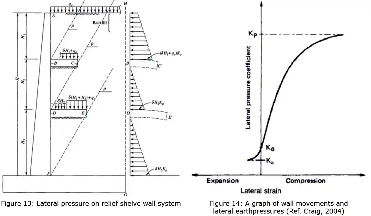
From this figure, it can be clearly observed that due to breaking of pressure wedge/failure plane, the total lateral force acting on the relief-shelve wall is very less as compared to the conventional walls (to say it in a layman’s language, a big triangular pressure diagram gets split into smaller triangles). Higher the heights–more is the reduction in the lateral force as compared to the conventional wall! In addition, the soil weight above relief-shelve slab increases the safety. Due to such interesting facts, the overall concrete required in relief-shelf wall is much lesser than the conventional walls (Lonkar and Narule, 2021). Some engineers have apprehension as the Coulomb’s earth pressure wedge may form or get shifted after the slab ends (Padhye and Ullagaddi, 2011); they need not worry as the actual behavior is confirmed by most of the research workers through physical scaled model as well as sophisticated FEA models, explained later. In India couple of companies have acquired patents towards this system of design and provide it under names such as ‘Graviloft system’ and ‘Introjected Wall’ etc., which are all the same versions of relief-shelve walls. Generally, relief-shelve wall proves to be economical for heights greater that 6 to 8m or so. Various research workers have found several aspects contributing to better behavior and economy; some of them are listed below:
It should also be noted that these zones are dynamic in nature (i.e. they shift their position every hour as per the changes in loading – especially surcharge and pore water pressures is the soil behind).The diaphragm wall designers (bottom-up method) in UG metro projects know this phenomenon very well.
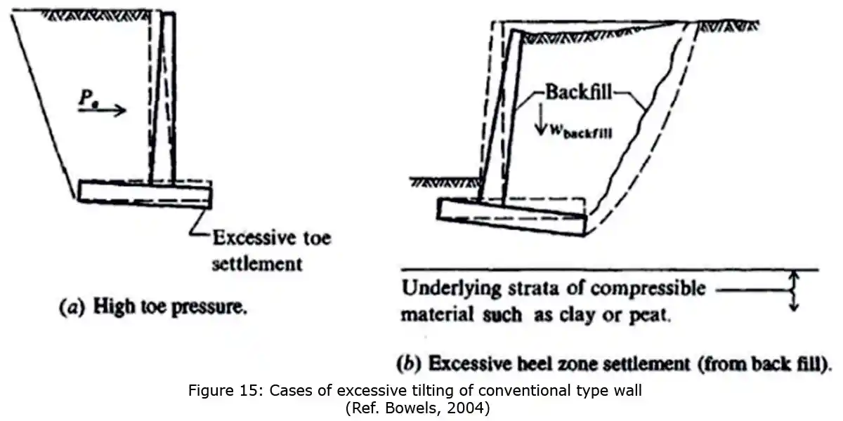
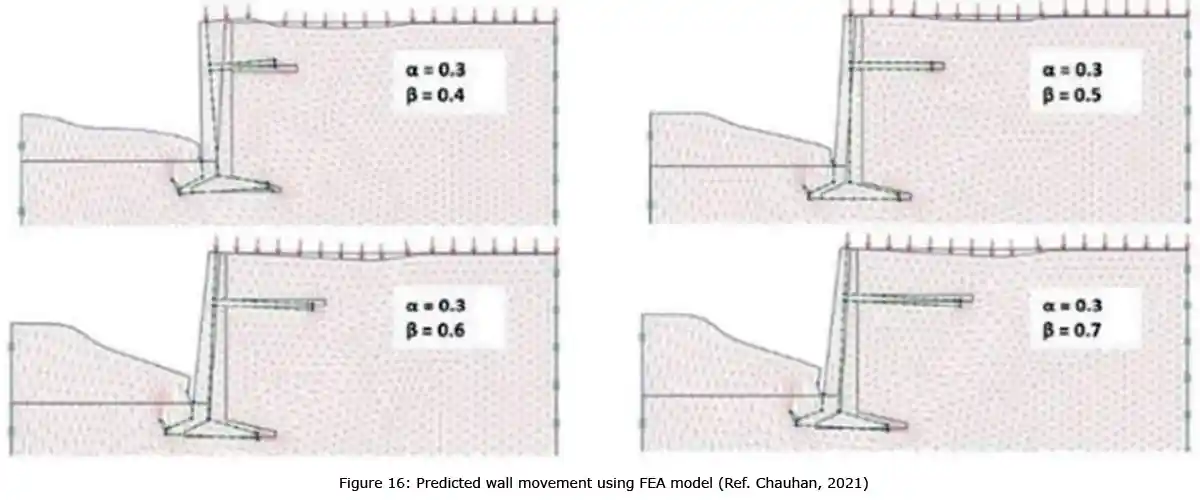
For tall retaining walls, the mode of failure is often a matter of concern and designers/consultants often try to be very conservative during the design process. Apart from sliding, overturning, and base pressure checks the global stability of structure (slip circle) is also important. The location of the vertical component of earth pressure ‘kv’ specified in various reference texts (including IRC and IRS guidelines) differs! Hence, the proof checking consultants often ask the design consultants to verify the design using all possible variables, and their combinations, and finally adopt the most ‘conservative output’. Fig. 15 and 16 respectively show the various failure modes for conventional RCC wall and relief-shelve walls.
Construction Features of Relief-Shelf Wall
The length of the relief shelf wall could be extended as long as possible (provided the height of the wall remains greater than about 6 to 8m at every cross section). Note that the height of a retaining wall is measured from ground level on passive side/lower side till the top of wall or the ground level on higher side (i.e., the embedded depth is not counted as effective height). Wherever height is lesser, then conventional type of walls can be provided in that portion. Along length of relief shelf wall, a narrow expansion joints (about 10 mm wide) at every 30 m intervals are recommended across full height. This joint is usually filled with compressible material like thermocoal, cork, or tar paper, but must ensure water tightness in the long run. In hilly areas/valleys the height of the wall may be maximum at the center and kept tapering (reducing) towards both the ends. In such cases, the panels between the two expansion joints (i.e., of 30 m or less) may have footings provided in stepped fashion.
Also note that beyond end points of height lesser than 8m, a conventional type of retaining wall may be continued after an expansion joint. The founding depth could be decided as per the guidelines of open foundations prescribed by IRC-78 (cl. 705.2). Regular weep holes of 100 mm2 at 2 m c/c spacing are provided in the stem (vertical face wall) behind which a regular geotextile / filter media is provided to facilitate drainage of pore water. Usually, in the case of conventional walls the base width required is about 0.6 to 0.7 times the height of wall; whereas in the case of relief-shelf walls it could range between 0.3 to 0.5 times the height of wall. Hence, there is substantial saving in the space as well as construction materials. Planning engineers/site engineers/land surveyors can plan the construction space and activities accordingly. The back fill is laid and thoroughly compacted in layers of 0.5 to 0.6 m thickness each. In the case of a small standalone wall structures, some designers recommend constructing a cross wall at both the ends of main relief-shelve wall to avoid spillage of confined soil fill.
Indian Projects
This system has been used in India almost since the past 15 years, for wall heights ranging from 6 m to 30 m. Indian railways, PWD Maharashtra, NHAI, MIDC, CIDCO, Godrej, Mahindra and Mahindra, JSW, Puranik builders, LODHA builders, Larsen and Toubro and a couple of more eminent organizations have effectively adopted this system at a few of their sites. To increase the applicability of relief-shelve system in one of the projects, one system provider used geotextile layers in the retained earth which enhanced the stability to fill to a greater extent and further reduced the actual force exerted on the wall to almost half. This aspect has not been experimentally verified yet, using instrumentation like sensor or strain gauges. Although the principle behind the relief-shelve system is so well established, its implementation in Indian industry has not been fully adopted. It may be due to the possible reasons: (i) the rare site conditions where the system can be adopted i.e., wall heights greater than 10 m or 20 m, (ii) the prejudice of certain clients, consultants, proof checkers, or government officials towards adopting new technology, (iii) the lack of awareness within the industry, (iv) due to copyright aspects, or (v) may be the fear of failure endorsed by a few research workers in their literature. One or combination of these factors could be the reason/s behind lack of progress, lack of propagation, lack of popularity of relief wall system in Indian Industry. Some of the successfully executed projects using relief shelve system by M/s. Savi Infra, Pune, are shown in Fig.17.
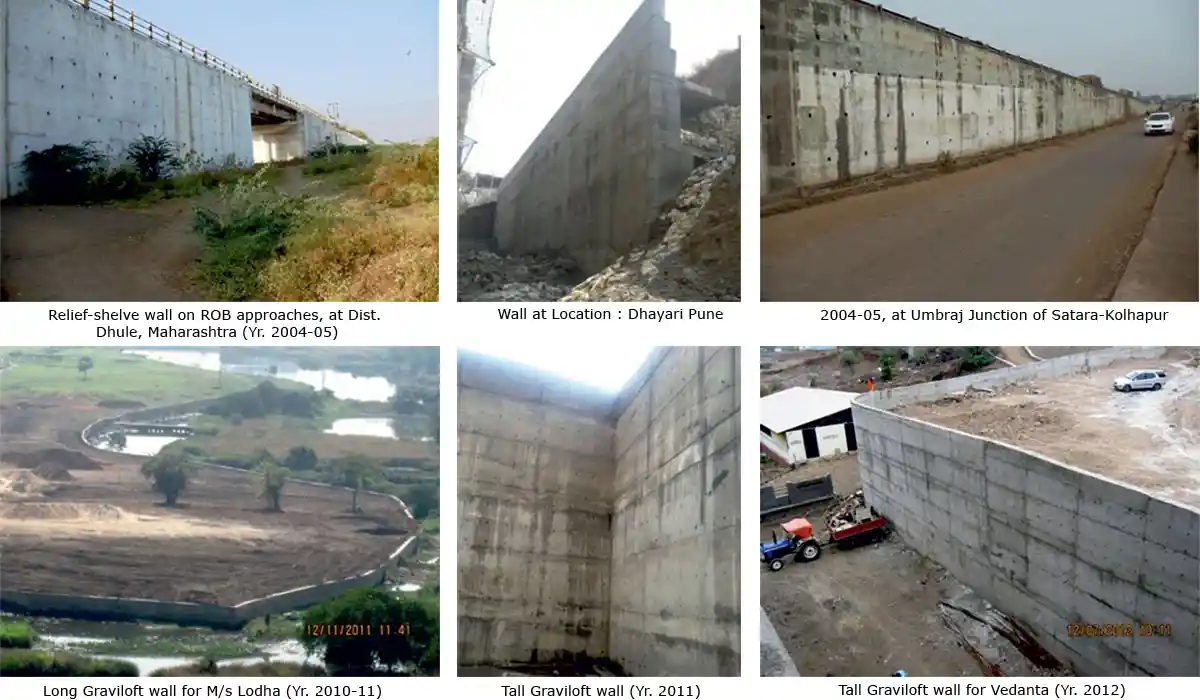 Figure 17: Some of the projects by Graviloft technology (Ref. 18 and M/s SAVI Infrastructure, Pune)
NHAI had used relief-shelve wall for the first time during 2004-05, at Umbraj Junction of Satara-Kolhapur four laning section of NH-4 (See Fig. 17). Similarly, L&T used the relief shelve wall in curved alignment in ghat stretch of Mumbai-Goa highway widening works, for the first time during 2020/21 for PWD-Maharashtra. One of the researcher papers has reported a failure case study from a relief-shelve wall somewhere in Hyderabad area with interesting findings and proposed solutions. Other than this, there is no evidence of failure of this type of walls.
Codes & Standards, Design Aids, Guidelines & Research Work
Till date, the full potential of relief shelve wall system, is not explored by the industry. The attempts made by a few system providers to approach MORTH / NHAI / IRC to form a separate code or identify this as a ‘New technology’ are still not turning into a fruitful result. Due to this, the designers and system providers have to depend on the judgments, past experience and/or purely computer FEA models (in high-end programs like - Plaxis 2D /FLAC3D/ABAQUS /GEOSTUDO / GEO5 / SAP-2000; one researcher even tried to model using STAAD plate elements) and general provision of IS 456, IRC 40, IRC 78, IS 14458 codes. Figure 18 shows a few of such research studies using different FEA analysis / design software programs.
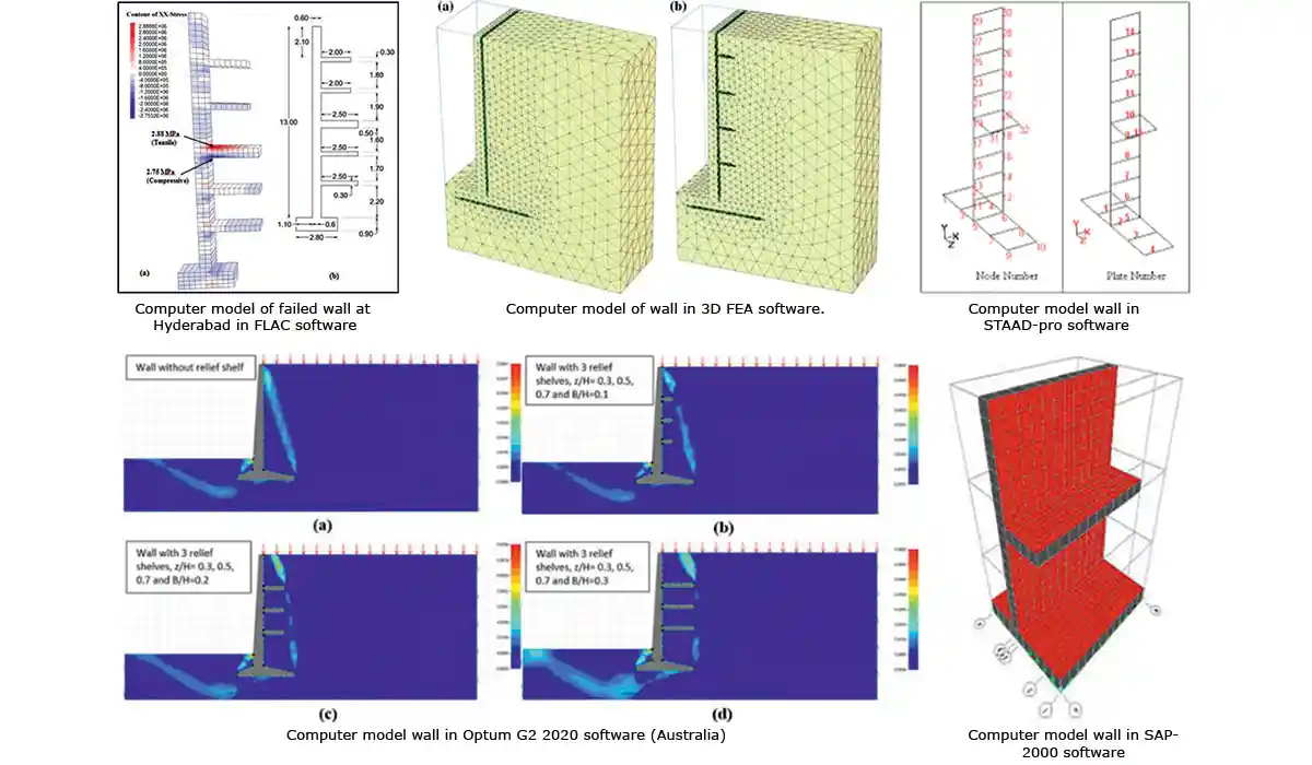 Figure 18: Models of Relief shelve walls by many researchers using different software programs
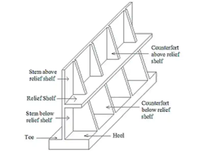 Figure 19: Relief shelve walls with counterforts
From the above discussions, it may be clear that a lot of academic research has taken place on the relief shelve walls in the past five years. Several software programs and research papers are available on the topic. Tonne and Mohite (2015) even recommended relief shelve walls with counterforts (see Fig.19), but the necessity of counterforts in the presence of relief shelve slabs is questionable (may be ineffective). In one of the real life road projects one system supplier recommended use of a rectangular shaped plinth beam on the buried edge of relief-shelve slabs, saying that it will act like an anchor (effectiveness of such beams is doubtful and even difficult to construct at site; and hence needs experimental verification!). Apart from this, the thickness of relief-shelve slab could be debated (thicker and stiff or thinner and flexible, which is better).
Figure 19: Relief shelve walls with counterforts
From the above discussions, it may be clear that a lot of academic research has taken place on the relief shelve walls in the past five years. Several software programs and research papers are available on the topic. Tonne and Mohite (2015) even recommended relief shelve walls with counterforts (see Fig.19), but the necessity of counterforts in the presence of relief shelve slabs is questionable (may be ineffective). In one of the real life road projects one system supplier recommended use of a rectangular shaped plinth beam on the buried edge of relief-shelve slabs, saying that it will act like an anchor (effectiveness of such beams is doubtful and even difficult to construct at site; and hence needs experimental verification!). Apart from this, the thickness of relief-shelve slab could be debated (thicker and stiff or thinner and flexible, which is better).
Now, the time has come where the practitioners in the industry should move to next step i.e., from research papers to real life implementation and experience the real behavior of this system. Hope this paper will inspire/create awareness among the ‘Practitioners’ in industry to use this information on relief-shelve walls in their upcoming projects.
Conclusions
Engineers are, in general, very creative and enthusiastic and have explored in the past using new materials, structural forms, studying the loadings and the behaviors of structural systems, etc., right from simple bullock cart to complex super-sonic air vehicle or high-speed rail; from simple soil and rock mass to smart / nano materials. One such intelligent invention in the history of earth retention methods is the ‘Relief-Shelve’ walls. The relief-shelve-wall breaks or splits the formation of shear failure planes and thus reduces the lateral load acting on the wall to a significant extent. From the executed works in past 15 years, it can be observed that saving of about 15 to 30% can be easily obtained by using relief-shelve walls as compared to conventional retaining walls. The technology does not require any skilled workers or special formwork or big equipment like cranes or vibro-hammers. It is extremely suitable for hilly roads where the question of retaining high level soil fills often arises and where the ROW/land available for construction is restricted. Till date, lot of academic research has been done on these types of walls but the real-life implementation is lacking, and is much scattered and limited. Government officials / NHAI / PWD / MSRDC / RAILWAY, private sector consultants, and giant EPC contractors should step ahead and try this unique technology. The more we use – the more we learn – the more we benefit!
Acknowledgements
The author is thankful to the editor for inviting and giving an opportunity to write on such an important yet ignored aspect of engineering. The author also wishes to thank all the authors, research workers, and system providers for their literature and support.
References
 Er. Vivek G. Abhyankar is the Founder of SGAWings Civil Engg. Consultants and Advisor (OPC) Pvt. Ltd.; Fellow of Institution of Engineers (India), Fellow of IAStructE, Licensed Structural Engineer (MCGM) and life member of various professional Institutes (IRC, ISSE, IIBE, ACI, ICI, ACCE, ISRMTT, INSDAG, ASCE, NICEE, and SEFI). He is a Gold Medalist from the University of Mumbai in PG-Structures degree. He has over 23 years of rich experience in planning and design, detailing of various civil engineering structures (roads / metros / buildings / temporary works, etc.). He was a visiting faculty for Structural Engineering at VJTI, SPCE and has acquired vast experience in technical training for site engineers. He has written more than 30 technical papers on practical aspects of engineering and contributed 3 chapters in top rated books and guided more than 10 M.Tech., AMIE thesis. He has contributed to various professional initiatives in the corporate sector like E-Learning, Knowledge management, Engineers’ Day, standardization of construction inventory etc.
Er. Vivek Abhyankar, Founder, SGAWings Civil Engineering Consultant and Advisor (OPC), Mumbai
In a conventional gravity type wall, the wall resists the lateral load caused by a massive soil block behind, whereas in the relief-shelve system the overall soil block itself is split into smaller shelves/wedges/blocks with the help of ‘relief shelve slab’, resulting in substantial reduction of the lateral pressure acting on the wall. Hence, the overall size of components (stem thickness, width of footing etc) required for the wall are significantly reduced. This can also result in substantial saving in the material quantity, construction time, and overall cost, as well as reducing the risks involved.
In conventional retaining walls, after several years, due to either overloading, or material creep, or even design or construction faults, if the wall starts leaning or bulging, then a ‘progressive collapse’ may eventually occur. But in the case of the ‘relief-shelve’ system, if the wall starts leaning, then the factor of safety increases slightly due to the deformed shape, and the collapse gets delayed (ductile failure/converging behavior).
Due to these unique actions, this wall is suitable for places where the required height of the wall is high (10m to 30m or more) but the available width of land is restricted (as on hilly roads). However, certain cautionary points have to be remembered by the designers, planners, and site engineers so that they can thoroughly understand and use this technique in their ongoing/upcoming projects and avail the maximum benefits for the project, company, and for the nation at large.
Introduction
While working on civil engineering projects, we rarely encounter a flat earth surface; the land is often undulating, uneven, wavy, hilly, or near a valley, a gorge; or with ponds, puddles, rivers, embankments; or touching an existing road, railway line or a building. Especially in long length project stretches like roads, railways, runways etc, the level differences of land are routine. At such locations we use ‘earth retaining walls’ to maintain the level difference between two sides of soil by laterally holding the soil/fill on the higher side.
Civil engineering professionals are generally aware about various conventional earth retention systems such as Stone masonry walls, PCC block walls, Timber shoring, Reinforced concrete retaining walls (flat surface, counterfort type, buttress type, arch type), Steel pile shoring (cantilever/anchored/strutted), contiguous pile wall, secant pile wall, diaphragm / slurry walls, Reinforced Earth (RE) panels, gabion walls, crib walls, and hollow box returns. Each of these types consume different materials viz. steel, concrete, stone, timber, geotextile, but often work on similar fundamentals to resist the lateral pressure caused by the soil; and each of them have certain merits and limitations. These systems can be used ‘in isolation’ or ‘in combination’ with other system/s or technologies (for example, with ground anchors, soil nails, or two materials together (a hybrid system) depending on site conditions. Each of these types and the resulting combinations have certain benefits and limitations.
The retained soil has a natural tendency to become flatter, and while doing so it exerts enormous lateral pressure on the retaining wall holding or retaining the soil. Hence, we need to apply stability checks against (a) overturning, (b) sliding, and (c) base pressure to the proposed structure of the wall. Due to earth pressure, the wall gets deformed or displaced. When the displacement occurs away from the retained soil mass (easing the soil particles) then it is called ‘active earth condition’. In certain cases, part of wall or whole wall moves towards the soil mass itself; such a case is called ‘passive earth condition’ (where the retained soil mass gets compressed and hence offers a large resistance to wall movements).
Respective coefficients are called as active (ka) or pass (kp) earth pressure coefficients. In certain cases, in spite of the soil mass exerting pressure on structure it doesn’t move (like a buried pipe or a box culvert or an underpass structure), such a case is called as ‘at rest’ condition and the respective coefficient is called as at-rest coefficient ‘k0’. The magnitude of lateral pressures (ka / kp / k0) depends on the (i) type of soil, (ii) surcharge loads, (iii) shape of the walls – height, width, inclination of back (earth face) and base, founding depths, intermediate struts, (iv) water level / pore pressure / and drainage arrangements. Based on combination of these factors two solutions are available, namely– Columb’s solution (CS) and, Rankine’s solution (RS). The difference between magnitude of ka, k0 and kp is graphically explained in a later figure (see Fig.14).
The concept of ‘relief-shelve’ wall was established almost sixty years back in the 1960s. Most of the initial attempts to implement it in real life situation, could not succeed, but certainly gave a lot of information about the behavior of these types of walls. Unfortunately, the overall attempts to implement it in the industry got limited/ignored. In the past ten years or so, in India various attempts were made to implement this technology in real life projects- including a couple of the author’s own works. The lateral earth pressure in the case of conventional and ‘relief-shelve’ wall is shown in Fig.1.
Figure 1: Lateral pressure (a) on conventional cantilever wall (b) on relief shelve systemBrief Review of Conventional Earth Retaining Walls
Before discussing the relief-shelf system, the conventional types of earth retaining walls are briefly described below.
Figure 2: Typical Stone Masonary wallStone masonry walls are suitable from 0.5 m to 2 m heights. Strong binding mortar and long through / key-stones are required in the construction. For taller walls, engineers use reinforcement rods in place of ‘key-stones’. In the case of non-availability of stones, engineers often use ‘PCC blocks’ for making walls. For drainage and reduction of pore water pressure, weep holes and filter media is recommended. Expansion joints are also given at certain intervals.
Figure 3: Typical Timber ShoringReinforced Concrete Wall – Cantilever type: (Fig.4) They are very much preferred due to fast construction. But the base width required is very large like stone masonry wall (gravity type walls). Height is limited to about 5 to 10m. These types of walls can avail the benefit of soil weight on active side by extending the heel slab. They have better monolithic body than the stone masonry.
Sometimes the wall height is less but the intensity of lateral pressure is higher (may be inclination of upper side ground or larger surcharge load on the upper side). In such case, to avoid sliding of the wall, a monolithic vertical extension called as ‘shear-key’ is provided in the base slab.
Figure 4: RCC cantilever wallCounterfort / Buttressed wall (Fig.5): When the height of wall increases the thickness of cantilever stem also increases proportionately (due to increase in the bending moment due to lateral soil pressure). In such case, instead of providing flat or a plane rectangular cross-section of stem (in plan), monolithic stiffeners can be cast (which looks like a ‘T-shaped cross section in plan’), these monolithic stiffeners are called ‘counterforts’ or ‘buttresses’ depending on their direction with respect to retained soil fill.
Figure 5: RC counterfort type wallContiguous (touching piles) & Secant pile wall (Fig.7): These walls comprise of closely driven / touching piles. They are slow to construct as compared to other types, although can sustain larger loads. They are most suited for entry/exists of underground metro stations or deeper cross passages, etc. Due to possible construction inaccuracies (i.e., gaps between piles during driving), contiguous piles are preferred for temporary works than permanent works.
Figure 6: Typical Steel sheet pile wallReinforced earth (RE) type wall (Fig.8): These types of walls look elegant and require sophisticated construction. They are equally costly, and not preferred in case of permanent exposure to water (baring a few exceptions). Slow to construct, preferred for bridge abutments, ramps, approaches, entry exists to airports, etc. They can be constructed up to certain limited heights (say, 10 to 11m); they also require firm ground (better SBC) and engineered backfill as compared to other gravity walls. They utilize the friction between soil and anchors / geotextile buried in the retained soil behind. They require firm drainage arrangement unlike other types where weep holes can be given.
Gabion wall (Fig.9): They are made up from masses of densely packed stone pieces, manually packed in steel wire mesh crates or boxes. They are more environment friendly. Due to the porous nature, they do not require a separate drainage arrangement like weep holes (however geotextile is provided on the backside to arrest wash-out of soil particles). They are suited for permanent as well as temporary works. Faster to construct as compared to RCC or piled walls. No separate cranes or hammers are required; but highly skilled craftsmen are required for packing the stones as the efficiency depends on the packing of stones. As compared to other types of retaining walls they are more flexible; can be used up to about 15m.
Crib Wall (Fig.10): Crib walls are formed from interlocking precast units or timber sleepers (arranged orthogonally in each layer) to form a series of hollow boxes. The boxes are filled with selected granular material to form a retaining wall. They are popularly used in many countries in gardens or even road projects. They are suitable for shall heights from 2m to 7m.
Hollow Box type return / abutment walls: Sometimes, in tall bridge abutments instead of using a single solid plate type RCC wall, a hollow box type RCC structural arrangement is used; it comprises of two or more flat vertical walls [right from footing raft till Finished Road level (FRL) supported with a beam column grid work. They have a larger moment of inertia as compared to solid section of wall; thus, there is a material saving but land / space required is larger.
Figure 10: Crib wallHybrid Systems: From above solutions it can be understood that from 0.5m up to 15m height, several solutions are available for soil retention. For larger height of retention, often designers prefer a stepped fill, but it consumes much larger land; stability of such large embankments could also be of concern. Sometimes (rarely), engineers are forced to use hybrid type of wall for further larger heights (say 20m) which contains a combination of any two options described above e.g., (i) Gabion wall on the top of RCC wall or (ii) an RE wall over piled wall etc. (as per the site conditions). Approval of such walls and to ensure their longevity is a challenging issue. Hybrid walls are useful for larger heights but may not be economical; also, they include the limitations of both the systems, together for the said project. Also, it could be a potential risk in high seismic zones. In such situations, the relief-shelve wall is a most suitable option at highly affordable price.
Figure 11: Retaining wall using Steel Containers (Ref. HCC Year 2003)Engineers are so creative, that they keep exploring available materials and structural forms in the nature and life in general, for the benefit of society (in terms of - cost, construction time, ease, efficiency, aesthetics, and longevity). One such crude, yet creative application can be seen in Fig. 11, where the author had used empty steel cargo containers to retain the soil embankment in a crushing plant of one road project in India. The wall performed very well but it is suitable only for limited life (say, 3 to 5 years). Of course, it also requires availability of old empty scrap steel containers (otherwise would prove to be very costly). Even aesthetically they are not very pleasant; also consume huge space as compared to conventional walls.
Use of Geofoam Behind Retaining Walls
From the discussion till now, it may be clear that the large soil masses/blocks/embankments behind the earth retaining walls cause a huge lateral force on the structure of the wall. Controlling, restricting or reducing these lateral pressures is the sole aim in the earth retaining technology. As stated earlier, engineers always find innovative ways to solve engineering problems. ‘Geofoam’ is yet another such solution. Geofoam is expanded polystyrene or extruded polystyrene manufactured into large lightweight blocks. These blocks vary in size but are often found to be of size 2 m × 0.75 m × 0.75 m. The primary function of geofoam is to provide a lightweight void fill below a highway, bridge approach, embankment, or parking lot (ref. Fig. 12 below).
History of Relief-Shelf Walls
Relief shelve wall is yet another innovative technique of controlling the lateral pressure on the wall. It has almost 60 years of research history; but still unfortunately the technology did not get much approval in the industry. Relief-shelf wall system was first covered by Bowels in his famous book on ‘Foundation Analysis and Design’ (Bowels, 1996). Later Chaudhuri et al. (1973) demonstrated the principle a small-scale physical model tests (to prove how relief shelf wall can retain taller height of fills). A few senior professors / research scholars from Pune tried to demonstrate the phenomenon using similar scaled model. Yoo et al. (2012) and Moon et al. (2013) showed that the distribution of lateral earth pressure is a function of width and position of relief shelf on the wall. Liu et al. (2011) found that when the relief shelf is located below a certain depth, it does not contribute much to the lateral earth pressure reduction in upper part of wall. Some of the recent research works done at IIT-Bombay confirmed the effectiveness of the relief-shelve system but a few questions were raised on the soil pressure distribution (Chauhan, 2021, Chauhan et al. 2019, Chauhan and Murty, 2016).
Irrespective of the above points of difference – all the research workers have agreed on the fundamental of ‘breaking the shear failure plane/wedge’ using relief-shelves and the effectiveness of the system for tall retention heights (Refer list of papers mentioned at the end of this paper).
What is Relief-Shelve system and does it work Relief shelve wall comprises of a comparatively narrower footing at the base on which thinner wall stem is constructed in steps of about 2m to 3m, then back filled with soil; at the top of every step one small horizontal RC slab (called relief-shelves) is constructed which projects inside the soil fill, till a point to break the failure plane. Taller the height of retention – more will be the number of relief-shelves and effectiveness of the relief-shelve system. Fig. 13 shows such a typical multi relief shelve wall.
From this figure, it can be clearly observed that due to breaking of pressure wedge/failure plane, the total lateral force acting on the relief-shelve wall is very less as compared to the conventional walls (to say it in a layman’s language, a big triangular pressure diagram gets split into smaller triangles). Higher the heights–more is the reduction in the lateral force as compared to the conventional wall! In addition, the soil weight above relief-shelve slab increases the safety. Due to such interesting facts, the overall concrete required in relief-shelf wall is much lesser than the conventional walls (Lonkar and Narule, 2021). Some engineers have apprehension as the Coulomb’s earth pressure wedge may form or get shifted after the slab ends (Padhye and Ullagaddi, 2011); they need not worry as the actual behavior is confirmed by most of the research workers through physical scaled model as well as sophisticated FEA models, explained later. In India couple of companies have acquired patents towards this system of design and provide it under names such as ‘Graviloft system’ and ‘Introjected Wall’ etc., which are all the same versions of relief-shelve walls. Generally, relief-shelve wall proves to be economical for heights greater that 6 to 8m or so. Various research workers have found several aspects contributing to better behavior and economy; some of them are listed below:
- The total saving in cost of relief-shelve system (material + workmanship together) ranges from 15% to 30%.
- Most of the research workers have agreed upon the use of PCC (or nominally reinforced section) for the vertical stem of the wall rather than RCC (only one case study opinioned that in tall multi-shelve relief walls there is a possibility of wall bending towards fill side, especially in cohesive soils i.e., passive pressure may generate in certain zones).
- Due to reduced forces and lesser structure weight, base width required is almost half or lesser than that of conventional systems of the same height; even the safe bearing capacity (SBC) of soil required is lesser.
- The factor of safety in these walls is much higher than the conventional systems. They can be effectively used in higher seismic zones as well.
- As the relief-slab bends / deforms laterally, it starts gripping the backfill better; thus, it enhances the factor of safety. (This point is important especially when clients are worried or afraid of any particular layer/s of the backfill above the slab is/are not compacted well!). Of course this point is does not give permit or encourage engineers to keep the backfill loosely packed, otherwise the wall although may not collapse but deform excessively. This point can be used only as a last line of safety at the ultimate stage. Because, in case of loosely packed back fill the collapse will anyway occur, but in a convergent manner.
- Embedded length of the relief-shelve slab inside soil mass shall be carefully decided (too short length of slab is ineffective, whereas too long slab may also lead to increase in stresses in certain zones of the stem portion). Main intended function of these slabs is to break the shear failure plane and to form a new plane above them (and not to generate friction with soil like the case of RE wall geofabric. But it could be just an associated/secondary phenomenon).
It should also be noted that these zones are dynamic in nature (i.e. they shift their position every hour as per the changes in loading – especially surcharge and pore water pressures is the soil behind).The diaphragm wall designers (bottom-up method) in UG metro projects know this phenomenon very well.
For tall retaining walls, the mode of failure is often a matter of concern and designers/consultants often try to be very conservative during the design process. Apart from sliding, overturning, and base pressure checks the global stability of structure (slip circle) is also important. The location of the vertical component of earth pressure ‘kv’ specified in various reference texts (including IRC and IRS guidelines) differs! Hence, the proof checking consultants often ask the design consultants to verify the design using all possible variables, and their combinations, and finally adopt the most ‘conservative output’. Fig. 15 and 16 respectively show the various failure modes for conventional RCC wall and relief-shelve walls.
Construction Features of Relief-Shelf Wall
The length of the relief shelf wall could be extended as long as possible (provided the height of the wall remains greater than about 6 to 8m at every cross section). Note that the height of a retaining wall is measured from ground level on passive side/lower side till the top of wall or the ground level on higher side (i.e., the embedded depth is not counted as effective height). Wherever height is lesser, then conventional type of walls can be provided in that portion. Along length of relief shelf wall, a narrow expansion joints (about 10 mm wide) at every 30 m intervals are recommended across full height. This joint is usually filled with compressible material like thermocoal, cork, or tar paper, but must ensure water tightness in the long run. In hilly areas/valleys the height of the wall may be maximum at the center and kept tapering (reducing) towards both the ends. In such cases, the panels between the two expansion joints (i.e., of 30 m or less) may have footings provided in stepped fashion.
Also note that beyond end points of height lesser than 8m, a conventional type of retaining wall may be continued after an expansion joint. The founding depth could be decided as per the guidelines of open foundations prescribed by IRC-78 (cl. 705.2). Regular weep holes of 100 mm2 at 2 m c/c spacing are provided in the stem (vertical face wall) behind which a regular geotextile / filter media is provided to facilitate drainage of pore water. Usually, in the case of conventional walls the base width required is about 0.6 to 0.7 times the height of wall; whereas in the case of relief-shelf walls it could range between 0.3 to 0.5 times the height of wall. Hence, there is substantial saving in the space as well as construction materials. Planning engineers/site engineers/land surveyors can plan the construction space and activities accordingly. The back fill is laid and thoroughly compacted in layers of 0.5 to 0.6 m thickness each. In the case of a small standalone wall structures, some designers recommend constructing a cross wall at both the ends of main relief-shelve wall to avoid spillage of confined soil fill.
Indian Projects
This system has been used in India almost since the past 15 years, for wall heights ranging from 6 m to 30 m. Indian railways, PWD Maharashtra, NHAI, MIDC, CIDCO, Godrej, Mahindra and Mahindra, JSW, Puranik builders, LODHA builders, Larsen and Toubro and a couple of more eminent organizations have effectively adopted this system at a few of their sites. To increase the applicability of relief-shelve system in one of the projects, one system provider used geotextile layers in the retained earth which enhanced the stability to fill to a greater extent and further reduced the actual force exerted on the wall to almost half. This aspect has not been experimentally verified yet, using instrumentation like sensor or strain gauges. Although the principle behind the relief-shelve system is so well established, its implementation in Indian industry has not been fully adopted. It may be due to the possible reasons: (i) the rare site conditions where the system can be adopted i.e., wall heights greater than 10 m or 20 m, (ii) the prejudice of certain clients, consultants, proof checkers, or government officials towards adopting new technology, (iii) the lack of awareness within the industry, (iv) due to copyright aspects, or (v) may be the fear of failure endorsed by a few research workers in their literature. One or combination of these factors could be the reason/s behind lack of progress, lack of propagation, lack of popularity of relief wall system in Indian Industry. Some of the successfully executed projects using relief shelve system by M/s. Savi Infra, Pune, are shown in Fig.17.
Figure 17: Some of the projects by Graviloft technology (Ref. 18 and M/s SAVI Infrastructure, Pune)NHAI had used relief-shelve wall for the first time during 2004-05, at Umbraj Junction of Satara-Kolhapur four laning section of NH-4 (See Fig. 17). Similarly, L&T used the relief shelve wall in curved alignment in ghat stretch of Mumbai-Goa highway widening works, for the first time during 2020/21 for PWD-Maharashtra. One of the researcher papers has reported a failure case study from a relief-shelve wall somewhere in Hyderabad area with interesting findings and proposed solutions. Other than this, there is no evidence of failure of this type of walls.
Codes & Standards, Design Aids, Guidelines & Research Work
Till date, the full potential of relief shelve wall system, is not explored by the industry. The attempts made by a few system providers to approach MORTH / NHAI / IRC to form a separate code or identify this as a ‘New technology’ are still not turning into a fruitful result. Due to this, the designers and system providers have to depend on the judgments, past experience and/or purely computer FEA models (in high-end programs like - Plaxis 2D /FLAC3D/ABAQUS /GEOSTUDO / GEO5 / SAP-2000; one researcher even tried to model using STAAD plate elements) and general provision of IS 456, IRC 40, IRC 78, IS 14458 codes. Figure 18 shows a few of such research studies using different FEA analysis / design software programs.
Figure 18: Models of Relief shelve walls by many researchers using different software programsFigure 19: Relief shelve walls with counterfortsNow, the time has come where the practitioners in the industry should move to next step i.e., from research papers to real life implementation and experience the real behavior of this system. Hope this paper will inspire/create awareness among the ‘Practitioners’ in industry to use this information on relief-shelve walls in their upcoming projects.
Conclusions
Engineers are, in general, very creative and enthusiastic and have explored in the past using new materials, structural forms, studying the loadings and the behaviors of structural systems, etc., right from simple bullock cart to complex super-sonic air vehicle or high-speed rail; from simple soil and rock mass to smart / nano materials. One such intelligent invention in the history of earth retention methods is the ‘Relief-Shelve’ walls. The relief-shelve-wall breaks or splits the formation of shear failure planes and thus reduces the lateral load acting on the wall to a significant extent. From the executed works in past 15 years, it can be observed that saving of about 15 to 30% can be easily obtained by using relief-shelve walls as compared to conventional retaining walls. The technology does not require any skilled workers or special formwork or big equipment like cranes or vibro-hammers. It is extremely suitable for hilly roads where the question of retaining high level soil fills often arises and where the ROW/land available for construction is restricted. Till date, lot of academic research has been done on these types of walls but the real-life implementation is lacking, and is much scattered and limited. Government officials / NHAI / PWD / MSRDC / RAILWAY, private sector consultants, and giant EPC contractors should step ahead and try this unique technology. The more we use – the more we learn – the more we benefit!
Acknowledgements
The author is thankful to the editor for inviting and giving an opportunity to write on such an important yet ignored aspect of engineering. The author also wishes to thank all the authors, research workers, and system providers for their literature and support.
References
- Acharya, M., Acharya, I.P. (2019) “Finite Element Analysis of RCC Cantilever Retaining Wall with and without Pressure Relief Shelf using Staad Pro”, Proceedings of IOE Graduate Conference, 2019-Winter, 6 pp.
- Balwan, R. J. and Kumbhar, A. (2011) “GraviloftRetaining wall - a Case study”, ICG Conf., Kochi.
- Bowels. J. W. (1996) Foundation Analysis and Design,5th Edition, McGraw Hill, New York.
- Chaudhuri, P.R., Garg, A.K., Rao, M.V.B., Sharma, R.N., Satija, P.D. (1973). “Design of retaining wall with relieving shelves”, IRC Journal, Vol. 35, No.2, pp. 289 - 325.
- Chauhan, V.B. (2021) “Limit analysis of the retaining wall with relief shelves under static surcharge loading using FEM” Sådhanå, Indian Academy of Sciences, Vol. 46, No. 135, 16 pp. https://doi.org/10.1007/s12046-021-01662-9
- Chauhan, V.B., Khan, R., and Dasaka, S.M. (2019) “Reduction of surcharge induced earth pressure on rigid non-yielding retaining wall using relief shelves”, in Geotechnical Applications, Edition Vol.4, I.V. Anirudhan and V. B. Maji (eds.), Springer-Singapore, https://doi.org/10.1007/978-981-13-0368-5_23
- Chauhan V. B. and Murty, D.S. (2016) “Behavior of rigid retaining wall with relief shelves with cohesive backfill”, 5th International Conference on Forensic Geotechnical Engineering, Dec. 8 to 10, IISc Bangalore .
- Craig, R.F. (2004) Craig’s Soil Mechanics, 7th Edition, Spon Press, London and New York, 447 pp.
- IRC SP10:2014.Guidelines for Design and Construction of Reinforced Soil Walls. Indian Roads Congress, New Delhi.
- IRC SP-116:2018. Guidelines For Design and Installation of Gabion Structures. Indian Roads Congress, New Delhi.
- IRC SP-48:1998. Hill Road Manual. Indian Roads Congress, New Delhi.
- IRC 78: 2014. Code of practice for Road Bridges – Foundations and Structures. Indian Roads Congress, New Delhi.
- IS14458: 1997. Retaining Wall for Hill Area – Guidelines (part 1 to 6), Bureau of Indian Standards, New Delhi.
- Liu, G., Hu, R., Pan, X., Liu Y. (2011) “Model tests on earth pressure of upper part wall of sheet pile wall with relieving platform”, Rock and Soil Mechanics, Vol. 32, No.2,pp. 103-110.
- Lonkar, S.S, and Narule, G.N. (2021) “Structural Performance of Relief Shelf in Cantilever Retaining Wall”, Journal of Engineering, Vol. 11, No.5, pp. 60-68.
- Moon, I. J., Kim, B. I., Yoo, W. K., and Park, Y. S. (2013) “Model tests for measurement of lateral earth pressure on retaining wall with the relieving platform using jumoonjin sand”, J. Korea. Acad. Industr. Coop. Soc., Vol.14, pp. 5923–
- Padhye, R.D. and Ullagaddi, P. B. (2011) “Analysis of Retaining Wall with Pressure Relief Shelf by Coulomb’s Method”, Proc. of Indian Geotechnical Conference, December 15-17, Kochi, pp. 671-673.
- Patil of Savi Infra, Youtube lecture on Garviloft system, delivered at ICI symposium, Pune.
- Rathi, H. and Ronghe, G. N. (2019) “Optimize Positioning of Relief Shelf in Cantilever Retaining Wall”, GRD Journal for Engineering, Feb., pp. 218-220.
- Shehata, H.F. (2016) ‘Retaining walls with relief shelves’, Innovative Infrastructure Solutions, Vol.1, No. 4, 13 pp.
- Tonne, V. R, and Mohite, P. M, (2015) “Optimization and Improvement in Stability of Counterfort Retaining Wall With Relief Shelf”, Int. Journal of Research in Engg. and Tech., Vol. 4, No.4, pp. 447-451.
- Vivek Abhyankar (2022)‘Indian Forts – A structural engineering Marvel’, NBM&CW, Vol. 27, No.9, Mar. pp.2-9.
- Winterkorn, H.F. and Fang, H.-Y. (1975) Foundation Engineering Handbook, Van Nostrand Reinhold, 751 pp.
- Yoo, W.K., Kim, B.I., Moon, I., Park, Y.S. (2012) Comparison of the lateral earth pressure on the retaining wall with the relieving platform by model test and numerical analysis. Journal Korea Academy Ind., Vol. 13, No.5, pp.2382–2389.
International Concrete Construction Technology Jan - Feb 2023