
Shrinkage, Creep, Crack-Width, Deflection in Concrete
The effects of shrinkage, creep, crack-width, and deflection in concrete are often ignored by designers while designing structural members. These effects, if not considered in some special cases such as long span slabs or long cantilevers, may become very serious and eventually cause damage to concrete elements.
Dr. Colonel. P Nallathambi
It is assumed that the effects and the requirements of shrinkage, creep, crack-width and deflection in concrete are inherently taken care of by the codal provisions by limiting the span/depth ratio. In some critical cases in special structures, these effects are very serious and may cause damage to concrete elements at a later stage. Excessive crack-width and deflections can cause wider cracks, which may lead to corrosion in steel, and affect the durability of concrete and the strength of structural members. This paper highlights the requirements and suggests methods to check and control crack-width and limit deflections in concrete elements.
Shrinkage in Concrete
Concrete shrinkage is the change in length per unit length and is a dimensionless number expressed as a percentage. Shrinkage is the shortening of concrete due to drying and is independent of applied loads. Shrinkage of concrete is time-dependent strain, measured in an unloaded and unrestrained specimen at a constant temperature. Shrinkage is conveniently expressed as a dimensionless strain (m/m) under steady conditions of relative humidity and temperature. Shrinkage in concrete can be classified as:
(a) Plastic shrinkage; (b) Drying shrinkage; (c) Autogenous shrinkage; and (d) Carbonation shrinkage.
Plastic Shrinkage: This is the contraction in volume due to the loss of water by evaporation from the surface of concrete while in the plastic state or by absorption by aggregates from the concrete (Shetty, 2005). In the case of floors and pavements, a large area of concrete is exposed to hot sun and drying wind, leading to evaporation of water on the wet concrete surface. When the concrete is made with high water/cementitious ratio, large quantity of water bleeds and accumulates on the surface, leading to greater the plastic shrinkage.
Drying Shrinkage: As the hydration of cement is an everlasting process, drying shrinkage is also an everlasting process, when concrete is subjected to drying conditions (Shetty, 2005). It is the loss of water held in gel pores that causes the change in the volume. Under drying conditions, the gel water is lost progressively over a period, as long as the concrete is kept in dry conditions (Shetty, 2005).
Autogenous Shrinkage: It is the shrinkage due to the chemical reaction between cement and water, known as hydration, and does not include environmental effects such as temperature and drying wind. Its magnitude is usually ignored in concrete when the w/c ratio is more than 0.40.
Carbonation Shrinkage: Carbon dioxide present in the atmosphere reacts in the presence of water during the hydration of cement. Carbonation shrinkage is due to the dissolution of crystals of calcium hydroxide. Calcium hydroxide (Ca(OH)2) gets converted to calcium carbonate and other cement compounds. As the volume of deposited calcium carbonate is less than the calcium hydroxide, shrinkage takes place. Carbonation of concrete results in increased strength and reduced permeability, but as the magnitude of carbonation shrinkage is very small; its effect is not much significant. However, when the depth of carbonation reaches steel reinforcements, the steel is susceptible to corrosion.
Factors Influencing Shrinkage of Concrete
Shrinkage is dependent on all the factors which affect the drying of concrete, including the relative humidity and temperature, the characteristics of the concrete mix (such as the type and quantity of the binder, the water content and water-cementitious ratio, the ratio of fine to coarse aggregate, and the amount, type, and shape of coarse aggregates), and the size and shape of the RC member (Gilbert, 2001). Other factors that affect shrinkage include elastic properties of the aggregate, curing methods, environmental conditions. For a given humidity and temperature, the total shrinkage is most influenced by the total amount of water present in the concrete at the time of mixing, and to a lesser extent, by the cement content (IS 1343:2012).
Influence of Concrete Ingredients on Shrinkage
The type of coarse aggregate used will have the most influence on the shrinkage properties of concrete. Aggregate with a high elastic modulus will produce low shrinkage concrete. Aggregates that contain clay minerals will affect shrinkage behaviour as well. Hard, dense aggregate can restrain the shrinkage of the cement paste. In contrast, using aggregate with higher compressibility can increase the shrinkage of the concrete mixture by about 120 to 150 percent. The properties of aggregate from various quarries should be considered if shrinkage is to be minimized. Using a large-size aggregate, optimizing the gradation of the aggregate, and combining aggregate sources to minimize gap-grading and corresponding paste content can reduce shrinkage of concrete.
Other factors which may have a significant impact on the shrinkage of concrete mixtures are use of shrinkage-promoting admixtures, presence of excessive fines such as silt, clay, and dirt in aggregates-which may increase the water demand, and the use of high-strength concrete (which is prone to plastic shrinkage). The cumulative effect of these factors is multiplicative and not additive. The specific impact of any set of materials on shrinkage is to be determined by laboratory testing.
Effects of Shrinkage in Concrete
Concrete shrinkage strain, which is usually considered to be the sum of the drying and chemical shrinkage components, continues to increase with time at a decreasing rate (Gilbert, 2001). Shrinkage of concrete is a contraction of a structural element due to loss of moisture. When concrete starts shrinking, the events that occur are: The reinforcing bars inside the concrete element resist shortening; Due to this, a curvature is formed in the element; Shrinkage is now pressing the steel to make the entire element contract (steel is experiencing compressive stress now); It transfers these stresses to concrete as tensile stress and may cause shrinkage deflection. If the reinforcement is not symmetrically placed, a shrinkage-induced curvature may develop. Even when the beam is unloaded, shrinkage in an unsymmetrically reinforced concrete beam or slab can produce deflections of significant magnitude (Gilbert, 2001). Clause 6.2.4.1 of IS 456:2000 recommends that the total shrinkage strain in concrete may be taken as 0.0003, in the absence of test data. Note that the maximum strain in concrete for bending is taken as 0.0035, whereas in compression it is limited to 0.002 (as per clause 38.1of IS 456:2000).
Virtually, all concrete is subject to some type of restraint due to steel reinforcement, formwork, subgrade and adjacent members. Each of these restraint types will produce gradually increasing tensile stress in the concrete, which may lead to time-dependent cracking, increases in deflection and widening of existing cracks. Widened cracks and excess deflection will cause durability issues such as corrosion of re-bars and strength reduction. The extent of shrinkage cracking depends on the degree of restraint to shrinkage, the extensibility and strength of the concrete in tension, tensile creep, and the load-induced tension existing in the member.
Both the Australian code, AS 3600:2018 and Clause 6.2.4.1 of IS 1343:2012, the design shrinkage strain is to be calculated as the sum of the autogenous shrinkage strain (εca) and the drying shrinkage strain shrinkage strain (εcd)
εcs=εca+ εcd (1)
The AS 3600:2018 suggests that the autogenous shrinkage strain may be computed as
εca= εcaf (1–e-0.7t) (2a)
Where t is the time after setting of concrete (in days) and εcaf is the final autogenous shrinkage strain given by
εcaf=(0.056fck-0.5)×50×10-6 for fck ≤ 62.5 MPa (2b)
εcaf=(0.064fck-1.0)×50×10-6 for fck > 62.5 MPa (2b)
At any time t after commencement of drying (in days), the drying shrinkage strain can be calculated as
εcd= k1× k2× εcdb (3a)
Where, εcdb is the basic shrinkage strain given by
εcdb=(0.9-0.004fck)×εcdbb (3b)
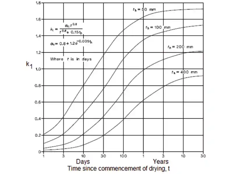 Figure 1: Shrinkage strain co-efficient (k1) for various values of th
In the absence of any measurements, AS 3600:2018 suggests that εcdbb may be taken as 800 × 10-6; k1 is obstained by interpolation from a figure given in AS 3600:2018 (See Fig. 1), and k4 is taken equal to 0.7 for and arid environment, 0.65 for an interior environment, 0.6 for a temperate inland environment, and 0.5 for a tropical or near-coastal environment, and th is the thickness of member. Note that it is important to prevent excessive drying of concrete between the commencement of casting and the application of curing.
Figure 1: Shrinkage strain co-efficient (k1) for various values of th
In the absence of any measurements, AS 3600:2018 suggests that εcdbb may be taken as 800 × 10-6; k1 is obstained by interpolation from a figure given in AS 3600:2018 (See Fig. 1), and k4 is taken equal to 0.7 for and arid environment, 0.65 for an interior environment, 0.6 for a temperate inland environment, and 0.5 for a tropical or near-coastal environment, and th is the thickness of member. Note that it is important to prevent excessive drying of concrete between the commencement of casting and the application of curing.
Cracking in concrete can be minimised if the gradually increasing tensile stress induced by shrinkage and by reduced by creep is at all times less than the tensile strength of the concrete (Gilbert, 2001). It should be noted that the relief offered by creep decreases with age. The presence of load-induced tension in uncracked regions accelerates the formation of time-dependent cracking. The control of such cracking requires two important steps. First, the designer should identify the shrinkage-induced tension regions, where shrinkage cracks are likely to get developed. Secondly, adequate quantity and distribution of anchored reinforcement must be provided in these regions to ensure that the cracks remain fine and the structure remains serviceable(Gilbert, 2001).
Prevention or Reduction of Shrinkage in Concrete
Shrinkage strain has to be kept within the limit (0.0003) to reduce crack-width and deflection and to improve the durability and strength of concrete. Methods adopted to reduce shrinkage in concrete are: Provision of shades during construction of slab to control the surface temperature. Dampening the sub-grade of concrete before placement, as concrete is prone to water absorption, over-dampening should be avoided. Starting wet curing (or steam curing) soon after finishing and using chemical admixtures to accelerate the setting time of concrete, will reduce shrinkage. Using aggregates containing excessive amounts of clay and having drying shrinkage properties should be avoided. Hard and rigid aggregates are difficult to compress, and hence they provide more restraint to shrinkage than softer ones. The water content of concrete should be kept as low as possible. Thus, shrinkage in concrete can be controlled by: Selection of proper materials such as aggregates, cement type, and admixtures; selection of mix proportion and cement content. The use of polypropylene/steel fibers or mesh, shrinkage-compensating concrete, shrinkage-reducing admix- tures and extensible concrete (the ability of the concrete to undergo extension due to tensile force without developing cracking) can reduce the shrinkage. More details on shrinkage and its effects may be found from Clause 19.4 of IS 456:2000 and Clause 6.2.4 of IS 1343:2012.
Creep in Concrete
Concrete creep is defined as the long-term deformation of a structure under a sustained load. Long-term pressure or stress on concrete can change its shape (sagging). The time-dependent deformation in concrete under permanent loads or Post Tension (PT) loads causes permanent displacement. Compressive creep is a physical phenomenon where the deformation of a member under a continuous load increases over time even without the application of additional loads. This deformation of concrete causes instantaneous strain. This time-dependent strain is called creep.
Creep is the tendency of all materials to deform permanently under the influence of stresses. When a load is applied to concrete, it experiences an instantaneous elastic strain which develops into creep strain if the load is sustained. Under sustained stress, with time, the gel (the product of hydration), the absorbed water layer, and the water held in the gel pores and capillary pores yields, flows and readjust themselves. Some movement also occurs due to the propagation of micro-cracks. These movements are the primary cause of creep deformation. Creep deflections can easily be observed in long concrete cantilever beams, if they are not designed for creep (Subramanian, 2019).
When concrete is loaded, the structure undergoes elastic and inelastic deformations. Elastic deformations occur immediately after the concrete is subjected to a given load, according to Hooke’s Law. Inelastic deformations increase with time as the concrete experiences a sustained load. This inelastic deformation, also known as creep develops rapidly and later the rate of increase slows appreciably with time. During the first month of sustained loading, approximately one-fourth to one-third of the ultimate creep takes place. As time proceeds, usually one-half to three-fourths of the ultimate creep occurs during the first half-year (Gambali and Shanagam, 2014). After many years, the creep strain typically attains values 2 to 6 times larger than the initial elastic strain.
The long-term modulus of elasticity (Ece) or the effective modulus of concrete is needed to include the effect of creep due to permanent loads. It is learnt that the value of creep coefficient θ is reduced with the age of concrete at loading. It may also be noted that the ultimate creep strain does εcr not include short-term strain εc.
Factors Influencing Creep
The factors that affect the creep of concrete are similar to the factors affecting shrinkage. Thus, creep of concrete is influenced by: magnitude of the applied stress and its duration, age and strength of the concrete at first loading, amount of cement paste, water/cementitious ratio, properties of aggregates and cementitious materials, size and shape of concrete specimen, amount of steel reinforcement, curing conditions, environmental conditions such as humidity during the period of use and temperature, and the volume to surface ratio of the members (ACI Committee 209.1R-05, ACI 209R-92). When the concrete is loaded, the specimen undergoes internal properties such as the closure of voids in the concrete, viscous flow of the cement-water paste, crystalline flow in aggregates, and water flowing out of the cement “gel” due to drying and loading.
The exact mechanism of creep is still unclear and not well understood as yet. One of the major debates on creep of concrete is concerned with the role of water in creep, as some researchers argued that water is inessential to creep (Feldman 1972) while others believed that water is important (Powers 1968). When the concrete is loaded, the specimen undergoes internal properties such as closure of voids in the concrete, viscous flow of the cement-water paste, crystalline flow in aggregates, and water flowing out of the cement “gel” due to drying and loading. The creep behaviour of cementitious materials was reported to be internally associated with the viscous nature of its main hydration product, i.e. calcium– silicate–hydrate (C–S–H) gel. Water in C–S–H gel is classified into three types: capillary water, adsorbed water and interlayer water. When the concrete is loaded, the specimen undergoes internal properties such as closure of voids in the concrete, viscous flow of the cement-water paste, crystalline flow in aggregates, and water flowing out of the cement “gel” due to drying and loading. Aggregates play an important role in both creep and shrinkage. A well graded, coarser aggregate with low voids content, will reduce the effects of creep and shrinkage. Hard and dense aggregates, with a high modulus of elasticity and are not absorptive, were found to result in low shrinkage and creep rates. The type of curing procedure adopted, prior to loading, is also found to have an effect on creep. Atmospheric and high-pressure steam curing results in little creep when compared to the normal seven-day moist curing method. These two types of curing reduce the drying shrinkage by half as much as they reduce creep. Relative humidity and environmental conditions also affect creep. The volume-to-surface area ratio is important because it is governed by the evaporation rate in the movement of water outside the specimen.
The slump is a measure of the flow of concrete and is influenced by many factors, which also affect the creep. More aggregates will result in less creep as aggregate does not creep. But the cement paste contributes to creep. Aggregates also affect the stiffness of the system as more aggregate results in high stiffness which will be governed by the aggregate modulus. Haranki (2009) found that as the elastic modulus increases the creep coefficient decreases. Temperature also affects the creep. Rapid increase in creep takes place as the temperature increases to about 50°C, then a decrease takes place in creep to a temperature of about 120°C and again creep may increase up to about 400°C; The initial increase in creep is due to the rapid expulsion of evaporable water.
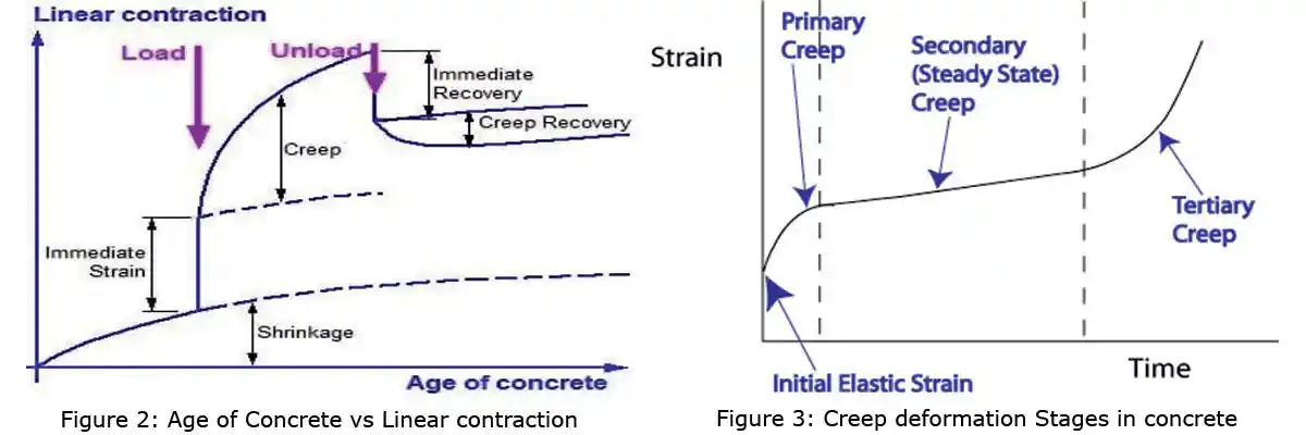
Creep is a time-dependent deformation of concrete by which it continues to deform, usually under compressive stress. The creep strains recover partly when the stresses are released. The creep recovery of concrete in terms of age of concrete vs linear contraction is in two parts as shown in Figure 2. The elastic recovery is immediate and the creep recovery is slow in nature. Thus, the long-term deflection will be added to the short-term deflection to get the total deflection of the structure. Figure 3 depicts the creep deformation stages in concrete (civil digital-concrete creep).
As mentioned in Clause 19.5 of IS 456:2000, the effects of shrinkage, creep and temperature are liable to affect materially the safety and serviceability of the structure. In ordinary buildings, such as low-rise dwelling units whose lateral dimensions do not exceed 45m, the effect due to temperature fluctuations and shrinkage and creep can be ignored in design calculations.
Effects of Creep on Concrete
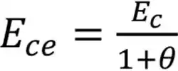
Creep of plain concrete does not by itself affect strength, but, due to very high stresses, when concrete strain due to creep exceeds the limiting strain, failure may occur. Effective creep modulus of elasticity, Ece, is taken as (Annex C of IS 456:2000)
(4a)
(4b)
fck is the cube strength of concrete, and θ is the creep coefficient which varies with the age of concrete, θ as per Clause 6.2.5.1 of IS 456:2000 is: for 7 Days- 2.2, 28 Days 1.6 and 365 Days- 1.1. More elaborate equations to calculate the creep coefficient of concrete are provided in IS 1343:2012. The reduction of Young’s modulus of the fresh concrete (Ec) at an early age (7-28 days) is about 82 -86 percent of the one-year Ec. Reduction of Ece will increase the crack-width and deflection, in turn, it affects the durability and strength of the concrete. The influence of creep on the ultimate strength of a simply supported, reinforced concrete beam subjected to a sustained load is insignificant, but deflection increases considerably and it may be a critical consideration in the design. Another instance of the adverse effects of creep is its influence on the stability of the structure through an increase in deformation and consequent transfer of load to other components. Thus, even when creep does not affect the ultimate strength of the component in which it takes place, its effect may be extremely serious as far as the performance of the structure as a whole is concerned.
The loss of pre-stress due to creep is well known and it is accounted for during pre-stressing. With the introduction of high-tensile steel, pre-stressing became a successful operation. In eccentrically loaded columns, creep increases the deflection and causes buckling. In the case of statically indeterminate structures, column and beam junction creep may relieve the stress concentration induced by shrinkage, temperature changes or movement of support. The creep property of concrete will be useful in all concrete structures to reduce internal stresses due to non-uniform load or restrained shrinkage.
In mass concrete structures such as dams, thick raft slabs, etc, because of differential temperature conditions between the interior and surface of the members, creep is harmful and may cause cracks in the interior parts. Therefore, all precautions and steps must be taken such that the increase in temperature does not take place in the interior of the mass concrete structure (Gambali and Shanagam, 2014).
Because of rapid construction techniques, concrete members will experience loads that can be as large as the design loads at a very early age; these can cause deflections due to cracking and early age low elastic modulus. Creep has a significant effect on both the structural integrity and the economic impact, if predicted wrong.
The individual limiting value of creep is not defined in codes but there is a need to limit the deformation/ deflection of the structure. The deflection shall generally be limited as: the final deflection due to all loads including the effects of temperature, creep and shrinkage and measured from the cast level of the supports of floors, roofs, and all other horizontal members, should not normally exceed span / 250 as per Clause 23.2 of IS 456:2000.
Crack-Width in Concrete
The occurrence of cracks in RC structures is unavoidable and the cracks form when the tensile stress in concrete exceeds its tensile strength (0.7√fck). Limiting the stresses in concrete components is important, from the aesthetic point of view, and also to ensure water tightness and safeguard the reinforcement against corrosion. Cracking causes significant increments in deflections in reinforced concrete members. This is caused due to the reduction of flexural stiffness at cracked sections and a reduction in moment of inertia (I) due to the cracking of concrete below the neutral axis. Cracks have a significant influence on serviceability, durability, aesthetics, and force transfer. Hence, an accurate estimation of the crack-width and their predictions are essential in the design of highly sensitive structures.
The crack-width of the concrete is limited for various reasons such as protecting the members from the aggressive environment, avoiding liquid contact with steel in liquid retaining structures, and providing better durability in important structures such as nuclear, space and marine structures. To meet the crack-width limitations, the stresses in steel have been kept low (0.55fy in the working stress method) accordingly adequate quantities of steel are provided. Special attention is required to limit the design crack-width as mentioned in clauses 35.3.2 & 43 of IS 456:2000, the code has included the formulae for the calculation of crack-width in Annex F.
Crack-width calculation is one of the serviceability requirements in structural members. The permissible crack-width varies from 0.10 mm to 0.30 mm depending upon the type of structure and environment. The IS Code has recommended that the surface crack-width should not exceed 0.3 mm for structures not subjected to an aggressive environment. However, if the structure is exposed to aggressive environments, the crack-width near the main reinforcement should not exceed 0.004 times the nominal cover to the reinforcement bars (this was recommended in an earlier version of IS 456). Some of the international codes that deal with this topic are: BS 8110-1997, IS 456-2000, ACI code 318:2019, GBJ 10-89 1989, BS EN 1992-1-1: 2004 and ECP 203-2007.
Crack-Width Calculations
A formula for the maximum crack-width incorporates many governing parameters such as the grade of steel, grade of concrete, area and percentage of steel reinforcement, diameter of bars, spacing of bars, yield stress of steel bars and concrete cover. The crack-width increases as the clear cover and the diameter of reinforcement bars increase, and as the load is increased the crack-width increases in all the cases. The crack-width calculation is a complex process. There is a fracture mechanics-based approach to calculating the crack-width. But the recommendations in the reinforced concrete design are simpler for day-to-day use in design checks. IS 456:2000, Annex F, gives a simplified procedure to determine crack-width. Maximum moment location in a beam or slab should be considered for the estimation of crack-width. For that particular section, any location along the periphery in the tensile region is selected. Usually, the crack-width is calculated at a point in the soffit, which is equidistant from two longitudinal bars. This point is the location of the maximum estimated crack-width.
Annex F of the IS 456:2000 recommends two procedures for the sectional analysis to calculate x and εm considering the tension stiffening effect. The first one is a rigorous procedure with the explicit calculation of tension carried by the concrete, where a portion in the tensile zone below the neutral axis is considered. The second one is a simplified procedure to calculate the steel stresses based on the analysis of a cracked section, and then reduce this stress by an amount equal to the tensile force generated by the triangular distribution.
It has been found that the actual crack widths in structures are highly variable. A scatter of the order of ± 50 per cent in crack widths was observed even in careful laboratory work. Moreover, a better crack control is obtained when the steel rebars are well distributed over the zone of maximum concrete tension. Hence, from the 1999 edition of the ACI 318 code, instead of a crack width formula, maximum bar spacing is specified directly. Thus, the spacing s of reinforcement closest to a surface in tension should not exceed that given by
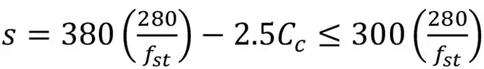
(5)
Where s is the center-to-center spacing of flexural tension reinforcement nearest to the extreme tension face, fst is the calculated stress in reinforcement at service load, and Cc is the clear cover of concrete.
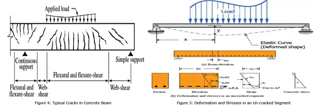
Acceptable Limits: The surface width of cracks for all members should not exceed 0.3mm. Where elements are exposed to aggressive environments the surface width of cracks shall not exceed 0.1mm or 0.004 times the nominal cover to the main reinforcement. For 50 mm cover, this amounts to 0.2 mm. The limits of crack-width for prestressing members are given in Table 10 of IS 1343:2012, in order that the appearance and durability of the structural elements are not affected. As per clause 20.3.2 of IS 1343:2012, the crack-width should not be more than 0.2 mm for moderate and mild environments, and 0.1 mm for severe environments. Once the crack-width is calculated, it should be checked whether the crack-width is within the permissible limits, depending on the environmental exposure of the structure. Types of cracks in concrete beams subjected to shear and bending moments (ACI Committee 318:2019) are shown in Figure 4. Typical deformation and stresses in an un-cracked segment are shown in Figure 5.
Estimation of Deflection of Concrete Members
The analysis of the structure to obtain the moments for calculating deflection is done under working or service loads. Several factors influence the deflection, which is difficult to assess and may affect the accuracy of results. These factors are: Inaccuracy in the idealisation of support conditions, difficulty in accounting for the extent of cracking in a member, difficulty in accessing the effect of finishes, partitions, and actual live loads, and variation in the modulus of elasticity of concrete.
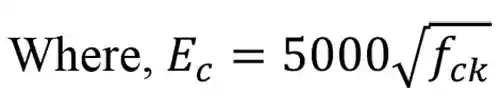
The method to calculate deflection is given in the Annex C of IS 456:2000. Total deflection in RCC beam and slab shall be the addition of short-term deflection under service loads, long term deflection due to shrinkage and creep (∆ = ∆L+∆S+∆C) as explained in the Annex C. Short-term deflection may be calculated by conventional methods for elastic deformation. The deflection of an RCC beam and slab for various loads, lengths, sizes and support conditions can be calculated using standard formulas for the deflection of a beam. In these formulas, the value of the modulus of elasticity adopted is Ec=5000√fck. Load w shall be service load and not factored load. Various moments of Inertia (I) such as the moment of inertia of the gross section (Igr for rectangular beam = bd3/12), moment of inertia of the cracked section (Icr for rectangular beam= b×x3/3+m×Ast×(d-x)2, where, x is the depth of neutral axis) and effective moment of inertia (Ieff) are computed for the calculation of deflection for RCC members. Formula for the calculation of Ieff is explained in Annex C of IS 456; Commonly, Icr≤ Ieff ≤Igr. Formulae for calculating the gross and cracked moment of inertia of singly and doubly reinforced rectangular and T-sections are given in Table 12.3 of Subramanian (2013). Note that ACI 318-19 uses a different formula for calculating Ieff.
The span/ depth ratio for various support conditions as mentioned in clause 23.2.1 of IS 456:2000 and is assumed to satisfy the vertical deflection limit criteria. If required, the total deflection of an RCC beam or slab can be calculated as per Annex C and compared with the permissible limit (Final deflection including effect of loads, shrinkage, creep and temperature) of L/250, or (Final deflection where partition walls or floor finishes being a guard against cracks is L/350 or 20mm) as given in clause 23.2 of IS 456:2000. Normal load conditions of residential and commercial RCC building can fulfil the serviceability deflection requirements, i.e. the Span/ depth ratio mentioned in clause 23.2.1 of IS 456:2000. Any abnormal loads, unusual support conditions, long cantilever beams, or slabs, etc, needs verification of the maximum deflection against permissible deflection specified in clause 23.2.1 of IS 456:2000.
Normally, RCC-framed structures are modelled in STAAD Pro software without slab elements. But, loads are assigned for the design of beams and columns. For longer beams (more than 6m in length), in addition to moments and shear forces, the deflection of the beams is to be checked and compared with limiting values. The slab may be modelled as a plate element in the STAAD model for long spans and maximum deflection can be verified from the STAAD model with a permissible deflection as per IS 456. Otherwise, deflection for slab element can be calculated as per Annex C of IS 456:2000 and compared with permissible deflection.
For a beam span of more than 6m, or slab having minimum width of more than 4.5m, cambering may used; i.e., shuttering height at the midpoint can be raised by about 10-15mm and concreting may be done. After the removal of the shutters, due to the self-weight of the concrete, the beam/ slab will become straight, and hence, the deflection will not be noticed and will be well within the limit. Adequate slab thickness shall be considered for vibration, and noise requirements, in addition to the deflection requirements. Otherwise, noise and vibration made by occupants at higher-levels can cause discomfort to the occupants at the lower-level.
Conclusions
Shrinkage reduces volume thereby causing tensile strain in the concrete, ultimately leading to cracks. Excessive crack-width and deflection affect the durability and strength of the concrete. Creep reduces the modulus of elasticity of the concrete, causing a reduction of strength and an increase in deflection. Crack- width and deflection in beam or slab members are worked out and compared with permissible value as per IS code for special structures to increase the durability and strength of the concrete. Crack-width and deflection calculations may not be mandatory for routine and small structures, because the allowable deflection by span/ thickness ratio mentioned in IS 456:2000 can take care of the required deflection in concrete beams and slabs. Limiting of yield steel (0.55fy) and limiting concrete strain (0.003) in the design of structures by working stress method can control the crack-width within the required limit in concrete members. But the calculation of crack-width and deflection is essential for special structures to reduce the damage to the structure over a period of time.
References
ACI Committee 209R-92, Prediction of Creep, Shrinkage, and Temperature Effects in Concrete Structures, American Concrete Institute, Farmington Hills, 47 pp.
ACI Committee 209.1R-05, Report on Factors Affecting Shrinkage and Creep of Hardened Concrete, American Concrete Institute, Farmington Hills, 12 pp.
Arvind , N. H. (2015). “Analytical Methods to Estimate the Crack Width in RC Beams”, International Journal of Innovative Research in Science, Engineering and Technology, Vol. 4, No. 7, July, pp. 6519-6530.
AS 3600:2018. Concrete Structures, Standards Australia Limited, Sydney, 262 pp.
Bažant, Z. P. (2001). “Prediction of concrete creep and shrinkage: Past, present and future”, Nuclear Engineering and Design, Vol.203, No.1, pp. 27–38.
Bhattacharjee, B., Concrete Technology, Lecture -27 Creep of Concrete, Indian Institute of Technology, Delhi.
Feldman, R. F. (1972). “Mechanism of creep of hydrated Portland cement paste”, Cement and Concrete Research, Vol. 2, No.5, pp. 521–540.
Gambali, A.K. and Shanagam, N. K. (2014). “Creep of Concrete”, International Journal of Engineering Development and Research, Vol. 2, No. 4, pp. 3800-3802.
Gilbert, R.I., (2001) “Shrinkage, Cracking and Deflection-the Serviceability of Concrete Structures”, Electronic Journal of Structural Engineering, Vol. 1, No.1, pp.2-14.
Haranki, B.(2009) Strength, Modulus of Elasticity, Creep and Shrinkage of Concrete Used In Florida, ME thesis, University of Florida, 176 pp.
IS 456:2000 Plain and Reinforced Concrete - Code of Practice, 4th Revision, Bureau of Indian Standards, New Delhi.
IS 1343:2012 Code of Practice for Prestressed Concrete, 2nd Revision, Bureau of Indian Standards, New Delhi.
Powers, T. (1968). “The thermodynamics of volume change and creep”, Matériaux et Construction, Vol.1, No.6, pp. 487–507.
Prakash, A.N. (2019) “Estimation Of Crack Width In Reinforced Concrete Members”, International Journal of Technical Innovation in Modern Engineering & Science, Vol. 5, No.5, May.
Shetty, M.S.(2005) Concrete Technology: Theory and Practice, S. Chand & Company Ltd. New Delhi, pp.340-348.
Subramanian (2013). Design of Reinforced Concrete Structures, Oxford University Press, New Delhi, 856pp.
Subramanian (2019). Building Materials, Testing and Sustainability, Oxford University Press, New Delhi, 788pp.
About the Author
 Dr. Colonel. P Nallathambi is the chief of M/S Sakthi Consultancy Pvt. Ltd., Chennai. His company is involved in designing of Government, Public and private buildings all over India. He is a graduate in Civil Engineering, Anna University in 1985 and obtained post graduate degree in Structural Engineering in 1988. He did Ph.D in Earthquake Engineering at Anna University, Chennai in Dec. 2017. He also obtained post graduate degree in operational management (MBA) and computer applications (MCA). He joined Indian Army in Jan 1988 and commissioned into Corps of Engineers. After one year of training in Indian Military Academy, Dehradun, he served subsequently in Punjab, J&K, Rajasthan, West Bengal and Assam border areas and took active part in many operations of Indian Army including IPKF in Sri Lanka. He has vast experience in bridging and combat engineering during his service. He had gained valuable experience in project execution, project management and structural design of various civil works while working in military engineering service for 9 years. He had three years teaching experience from 1992-95 in College of Military Engineering (CME), Pune. After completing 21 years of army service, he started his own civil and structural consultancy office in 2009. He is a member of many technical institutions and has actively participated in all activities of them. He has been writing articles from last seven years on a regular basis in many monthly magazines and shares his valuable experience which he has gained in the construction industry.
Dr. Colonel. P Nallathambi
It is assumed that the effects and the requirements of shrinkage, creep, crack-width and deflection in concrete are inherently taken care of by the codal provisions by limiting the span/depth ratio. In some critical cases in special structures, these effects are very serious and may cause damage to concrete elements at a later stage. Excessive crack-width and deflections can cause wider cracks, which may lead to corrosion in steel, and affect the durability of concrete and the strength of structural members. This paper highlights the requirements and suggests methods to check and control crack-width and limit deflections in concrete elements.
Shrinkage in Concrete
Concrete shrinkage is the change in length per unit length and is a dimensionless number expressed as a percentage. Shrinkage is the shortening of concrete due to drying and is independent of applied loads. Shrinkage of concrete is time-dependent strain, measured in an unloaded and unrestrained specimen at a constant temperature. Shrinkage is conveniently expressed as a dimensionless strain (m/m) under steady conditions of relative humidity and temperature. Shrinkage in concrete can be classified as:
(a) Plastic shrinkage; (b) Drying shrinkage; (c) Autogenous shrinkage; and (d) Carbonation shrinkage.
Plastic Shrinkage: This is the contraction in volume due to the loss of water by evaporation from the surface of concrete while in the plastic state or by absorption by aggregates from the concrete (Shetty, 2005). In the case of floors and pavements, a large area of concrete is exposed to hot sun and drying wind, leading to evaporation of water on the wet concrete surface. When the concrete is made with high water/cementitious ratio, large quantity of water bleeds and accumulates on the surface, leading to greater the plastic shrinkage.
Drying Shrinkage: As the hydration of cement is an everlasting process, drying shrinkage is also an everlasting process, when concrete is subjected to drying conditions (Shetty, 2005). It is the loss of water held in gel pores that causes the change in the volume. Under drying conditions, the gel water is lost progressively over a period, as long as the concrete is kept in dry conditions (Shetty, 2005).
Autogenous Shrinkage: It is the shrinkage due to the chemical reaction between cement and water, known as hydration, and does not include environmental effects such as temperature and drying wind. Its magnitude is usually ignored in concrete when the w/c ratio is more than 0.40.
Carbonation Shrinkage: Carbon dioxide present in the atmosphere reacts in the presence of water during the hydration of cement. Carbonation shrinkage is due to the dissolution of crystals of calcium hydroxide. Calcium hydroxide (Ca(OH)2) gets converted to calcium carbonate and other cement compounds. As the volume of deposited calcium carbonate is less than the calcium hydroxide, shrinkage takes place. Carbonation of concrete results in increased strength and reduced permeability, but as the magnitude of carbonation shrinkage is very small; its effect is not much significant. However, when the depth of carbonation reaches steel reinforcements, the steel is susceptible to corrosion.
Factors Influencing Shrinkage of Concrete
Shrinkage is dependent on all the factors which affect the drying of concrete, including the relative humidity and temperature, the characteristics of the concrete mix (such as the type and quantity of the binder, the water content and water-cementitious ratio, the ratio of fine to coarse aggregate, and the amount, type, and shape of coarse aggregates), and the size and shape of the RC member (Gilbert, 2001). Other factors that affect shrinkage include elastic properties of the aggregate, curing methods, environmental conditions. For a given humidity and temperature, the total shrinkage is most influenced by the total amount of water present in the concrete at the time of mixing, and to a lesser extent, by the cement content (IS 1343:2012).
Influence of Concrete Ingredients on Shrinkage
The type of coarse aggregate used will have the most influence on the shrinkage properties of concrete. Aggregate with a high elastic modulus will produce low shrinkage concrete. Aggregates that contain clay minerals will affect shrinkage behaviour as well. Hard, dense aggregate can restrain the shrinkage of the cement paste. In contrast, using aggregate with higher compressibility can increase the shrinkage of the concrete mixture by about 120 to 150 percent. The properties of aggregate from various quarries should be considered if shrinkage is to be minimized. Using a large-size aggregate, optimizing the gradation of the aggregate, and combining aggregate sources to minimize gap-grading and corresponding paste content can reduce shrinkage of concrete.
Other factors which may have a significant impact on the shrinkage of concrete mixtures are use of shrinkage-promoting admixtures, presence of excessive fines such as silt, clay, and dirt in aggregates-which may increase the water demand, and the use of high-strength concrete (which is prone to plastic shrinkage). The cumulative effect of these factors is multiplicative and not additive. The specific impact of any set of materials on shrinkage is to be determined by laboratory testing.
Effects of Shrinkage in Concrete
Concrete shrinkage strain, which is usually considered to be the sum of the drying and chemical shrinkage components, continues to increase with time at a decreasing rate (Gilbert, 2001). Shrinkage of concrete is a contraction of a structural element due to loss of moisture. When concrete starts shrinking, the events that occur are: The reinforcing bars inside the concrete element resist shortening; Due to this, a curvature is formed in the element; Shrinkage is now pressing the steel to make the entire element contract (steel is experiencing compressive stress now); It transfers these stresses to concrete as tensile stress and may cause shrinkage deflection. If the reinforcement is not symmetrically placed, a shrinkage-induced curvature may develop. Even when the beam is unloaded, shrinkage in an unsymmetrically reinforced concrete beam or slab can produce deflections of significant magnitude (Gilbert, 2001). Clause 6.2.4.1 of IS 456:2000 recommends that the total shrinkage strain in concrete may be taken as 0.0003, in the absence of test data. Note that the maximum strain in concrete for bending is taken as 0.0035, whereas in compression it is limited to 0.002 (as per clause 38.1of IS 456:2000).
Virtually, all concrete is subject to some type of restraint due to steel reinforcement, formwork, subgrade and adjacent members. Each of these restraint types will produce gradually increasing tensile stress in the concrete, which may lead to time-dependent cracking, increases in deflection and widening of existing cracks. Widened cracks and excess deflection will cause durability issues such as corrosion of re-bars and strength reduction. The extent of shrinkage cracking depends on the degree of restraint to shrinkage, the extensibility and strength of the concrete in tension, tensile creep, and the load-induced tension existing in the member.
Both the Australian code, AS 3600:2018 and Clause 6.2.4.1 of IS 1343:2012, the design shrinkage strain is to be calculated as the sum of the autogenous shrinkage strain (εca) and the drying shrinkage strain shrinkage strain (εcd)
εcs=εca+ εcd (1)
The AS 3600:2018 suggests that the autogenous shrinkage strain may be computed as
εca= εcaf (1–e-0.7t) (2a)
Where t is the time after setting of concrete (in days) and εcaf is the final autogenous shrinkage strain given by
εcaf=(0.056fck-0.5)×50×10-6 for fck ≤ 62.5 MPa (2b)
εcaf=(0.064fck-1.0)×50×10-6 for fck > 62.5 MPa (2b)
At any time t after commencement of drying (in days), the drying shrinkage strain can be calculated as
εcd= k1× k2× εcdb (3a)
Where, εcdb is the basic shrinkage strain given by
εcdb=(0.9-0.004fck)×εcdbb (3b)
Figure 1: Shrinkage strain co-efficient (k1) for various values of thCracking in concrete can be minimised if the gradually increasing tensile stress induced by shrinkage and by reduced by creep is at all times less than the tensile strength of the concrete (Gilbert, 2001). It should be noted that the relief offered by creep decreases with age. The presence of load-induced tension in uncracked regions accelerates the formation of time-dependent cracking. The control of such cracking requires two important steps. First, the designer should identify the shrinkage-induced tension regions, where shrinkage cracks are likely to get developed. Secondly, adequate quantity and distribution of anchored reinforcement must be provided in these regions to ensure that the cracks remain fine and the structure remains serviceable(Gilbert, 2001).
Prevention or Reduction of Shrinkage in Concrete
Shrinkage strain has to be kept within the limit (0.0003) to reduce crack-width and deflection and to improve the durability and strength of concrete. Methods adopted to reduce shrinkage in concrete are: Provision of shades during construction of slab to control the surface temperature. Dampening the sub-grade of concrete before placement, as concrete is prone to water absorption, over-dampening should be avoided. Starting wet curing (or steam curing) soon after finishing and using chemical admixtures to accelerate the setting time of concrete, will reduce shrinkage. Using aggregates containing excessive amounts of clay and having drying shrinkage properties should be avoided. Hard and rigid aggregates are difficult to compress, and hence they provide more restraint to shrinkage than softer ones. The water content of concrete should be kept as low as possible. Thus, shrinkage in concrete can be controlled by: Selection of proper materials such as aggregates, cement type, and admixtures; selection of mix proportion and cement content. The use of polypropylene/steel fibers or mesh, shrinkage-compensating concrete, shrinkage-reducing admix- tures and extensible concrete (the ability of the concrete to undergo extension due to tensile force without developing cracking) can reduce the shrinkage. More details on shrinkage and its effects may be found from Clause 19.4 of IS 456:2000 and Clause 6.2.4 of IS 1343:2012.
Creep in Concrete
Concrete creep is defined as the long-term deformation of a structure under a sustained load. Long-term pressure or stress on concrete can change its shape (sagging). The time-dependent deformation in concrete under permanent loads or Post Tension (PT) loads causes permanent displacement. Compressive creep is a physical phenomenon where the deformation of a member under a continuous load increases over time even without the application of additional loads. This deformation of concrete causes instantaneous strain. This time-dependent strain is called creep.
Creep is the tendency of all materials to deform permanently under the influence of stresses. When a load is applied to concrete, it experiences an instantaneous elastic strain which develops into creep strain if the load is sustained. Under sustained stress, with time, the gel (the product of hydration), the absorbed water layer, and the water held in the gel pores and capillary pores yields, flows and readjust themselves. Some movement also occurs due to the propagation of micro-cracks. These movements are the primary cause of creep deformation. Creep deflections can easily be observed in long concrete cantilever beams, if they are not designed for creep (Subramanian, 2019).
When concrete is loaded, the structure undergoes elastic and inelastic deformations. Elastic deformations occur immediately after the concrete is subjected to a given load, according to Hooke’s Law. Inelastic deformations increase with time as the concrete experiences a sustained load. This inelastic deformation, also known as creep develops rapidly and later the rate of increase slows appreciably with time. During the first month of sustained loading, approximately one-fourth to one-third of the ultimate creep takes place. As time proceeds, usually one-half to three-fourths of the ultimate creep occurs during the first half-year (Gambali and Shanagam, 2014). After many years, the creep strain typically attains values 2 to 6 times larger than the initial elastic strain.
The long-term modulus of elasticity (Ece) or the effective modulus of concrete is needed to include the effect of creep due to permanent loads. It is learnt that the value of creep coefficient θ is reduced with the age of concrete at loading. It may also be noted that the ultimate creep strain does εcr not include short-term strain εc.
Factors Influencing Creep
The factors that affect the creep of concrete are similar to the factors affecting shrinkage. Thus, creep of concrete is influenced by: magnitude of the applied stress and its duration, age and strength of the concrete at first loading, amount of cement paste, water/cementitious ratio, properties of aggregates and cementitious materials, size and shape of concrete specimen, amount of steel reinforcement, curing conditions, environmental conditions such as humidity during the period of use and temperature, and the volume to surface ratio of the members (ACI Committee 209.1R-05, ACI 209R-92). When the concrete is loaded, the specimen undergoes internal properties such as the closure of voids in the concrete, viscous flow of the cement-water paste, crystalline flow in aggregates, and water flowing out of the cement “gel” due to drying and loading.
The exact mechanism of creep is still unclear and not well understood as yet. One of the major debates on creep of concrete is concerned with the role of water in creep, as some researchers argued that water is inessential to creep (Feldman 1972) while others believed that water is important (Powers 1968). When the concrete is loaded, the specimen undergoes internal properties such as closure of voids in the concrete, viscous flow of the cement-water paste, crystalline flow in aggregates, and water flowing out of the cement “gel” due to drying and loading. The creep behaviour of cementitious materials was reported to be internally associated with the viscous nature of its main hydration product, i.e. calcium– silicate–hydrate (C–S–H) gel. Water in C–S–H gel is classified into three types: capillary water, adsorbed water and interlayer water. When the concrete is loaded, the specimen undergoes internal properties such as closure of voids in the concrete, viscous flow of the cement-water paste, crystalline flow in aggregates, and water flowing out of the cement “gel” due to drying and loading. Aggregates play an important role in both creep and shrinkage. A well graded, coarser aggregate with low voids content, will reduce the effects of creep and shrinkage. Hard and dense aggregates, with a high modulus of elasticity and are not absorptive, were found to result in low shrinkage and creep rates. The type of curing procedure adopted, prior to loading, is also found to have an effect on creep. Atmospheric and high-pressure steam curing results in little creep when compared to the normal seven-day moist curing method. These two types of curing reduce the drying shrinkage by half as much as they reduce creep. Relative humidity and environmental conditions also affect creep. The volume-to-surface area ratio is important because it is governed by the evaporation rate in the movement of water outside the specimen.
The slump is a measure of the flow of concrete and is influenced by many factors, which also affect the creep. More aggregates will result in less creep as aggregate does not creep. But the cement paste contributes to creep. Aggregates also affect the stiffness of the system as more aggregate results in high stiffness which will be governed by the aggregate modulus. Haranki (2009) found that as the elastic modulus increases the creep coefficient decreases. Temperature also affects the creep. Rapid increase in creep takes place as the temperature increases to about 50°C, then a decrease takes place in creep to a temperature of about 120°C and again creep may increase up to about 400°C; The initial increase in creep is due to the rapid expulsion of evaporable water.
Creep is a time-dependent deformation of concrete by which it continues to deform, usually under compressive stress. The creep strains recover partly when the stresses are released. The creep recovery of concrete in terms of age of concrete vs linear contraction is in two parts as shown in Figure 2. The elastic recovery is immediate and the creep recovery is slow in nature. Thus, the long-term deflection will be added to the short-term deflection to get the total deflection of the structure. Figure 3 depicts the creep deformation stages in concrete (civil digital-concrete creep).
As mentioned in Clause 19.5 of IS 456:2000, the effects of shrinkage, creep and temperature are liable to affect materially the safety and serviceability of the structure. In ordinary buildings, such as low-rise dwelling units whose lateral dimensions do not exceed 45m, the effect due to temperature fluctuations and shrinkage and creep can be ignored in design calculations.
Effects of Creep on Concrete
Creep of plain concrete does not by itself affect strength, but, due to very high stresses, when concrete strain due to creep exceeds the limiting strain, failure may occur. Effective creep modulus of elasticity, Ece, is taken as (Annex C of IS 456:2000)
(4a)
(4b)
fck is the cube strength of concrete, and θ is the creep coefficient which varies with the age of concrete, θ as per Clause 6.2.5.1 of IS 456:2000 is: for 7 Days- 2.2, 28 Days 1.6 and 365 Days- 1.1. More elaborate equations to calculate the creep coefficient of concrete are provided in IS 1343:2012. The reduction of Young’s modulus of the fresh concrete (Ec) at an early age (7-28 days) is about 82 -86 percent of the one-year Ec. Reduction of Ece will increase the crack-width and deflection, in turn, it affects the durability and strength of the concrete. The influence of creep on the ultimate strength of a simply supported, reinforced concrete beam subjected to a sustained load is insignificant, but deflection increases considerably and it may be a critical consideration in the design. Another instance of the adverse effects of creep is its influence on the stability of the structure through an increase in deformation and consequent transfer of load to other components. Thus, even when creep does not affect the ultimate strength of the component in which it takes place, its effect may be extremely serious as far as the performance of the structure as a whole is concerned.
The loss of pre-stress due to creep is well known and it is accounted for during pre-stressing. With the introduction of high-tensile steel, pre-stressing became a successful operation. In eccentrically loaded columns, creep increases the deflection and causes buckling. In the case of statically indeterminate structures, column and beam junction creep may relieve the stress concentration induced by shrinkage, temperature changes or movement of support. The creep property of concrete will be useful in all concrete structures to reduce internal stresses due to non-uniform load or restrained shrinkage.
In mass concrete structures such as dams, thick raft slabs, etc, because of differential temperature conditions between the interior and surface of the members, creep is harmful and may cause cracks in the interior parts. Therefore, all precautions and steps must be taken such that the increase in temperature does not take place in the interior of the mass concrete structure (Gambali and Shanagam, 2014).
Because of rapid construction techniques, concrete members will experience loads that can be as large as the design loads at a very early age; these can cause deflections due to cracking and early age low elastic modulus. Creep has a significant effect on both the structural integrity and the economic impact, if predicted wrong.
The individual limiting value of creep is not defined in codes but there is a need to limit the deformation/ deflection of the structure. The deflection shall generally be limited as: the final deflection due to all loads including the effects of temperature, creep and shrinkage and measured from the cast level of the supports of floors, roofs, and all other horizontal members, should not normally exceed span / 250 as per Clause 23.2 of IS 456:2000.
Crack-Width in Concrete
The occurrence of cracks in RC structures is unavoidable and the cracks form when the tensile stress in concrete exceeds its tensile strength (0.7√fck). Limiting the stresses in concrete components is important, from the aesthetic point of view, and also to ensure water tightness and safeguard the reinforcement against corrosion. Cracking causes significant increments in deflections in reinforced concrete members. This is caused due to the reduction of flexural stiffness at cracked sections and a reduction in moment of inertia (I) due to the cracking of concrete below the neutral axis. Cracks have a significant influence on serviceability, durability, aesthetics, and force transfer. Hence, an accurate estimation of the crack-width and their predictions are essential in the design of highly sensitive structures.
The crack-width of the concrete is limited for various reasons such as protecting the members from the aggressive environment, avoiding liquid contact with steel in liquid retaining structures, and providing better durability in important structures such as nuclear, space and marine structures. To meet the crack-width limitations, the stresses in steel have been kept low (0.55fy in the working stress method) accordingly adequate quantities of steel are provided. Special attention is required to limit the design crack-width as mentioned in clauses 35.3.2 & 43 of IS 456:2000, the code has included the formulae for the calculation of crack-width in Annex F.
Crack-width calculation is one of the serviceability requirements in structural members. The permissible crack-width varies from 0.10 mm to 0.30 mm depending upon the type of structure and environment. The IS Code has recommended that the surface crack-width should not exceed 0.3 mm for structures not subjected to an aggressive environment. However, if the structure is exposed to aggressive environments, the crack-width near the main reinforcement should not exceed 0.004 times the nominal cover to the reinforcement bars (this was recommended in an earlier version of IS 456). Some of the international codes that deal with this topic are: BS 8110-1997, IS 456-2000, ACI code 318:2019, GBJ 10-89 1989, BS EN 1992-1-1: 2004 and ECP 203-2007.
Crack-Width Calculations
A formula for the maximum crack-width incorporates many governing parameters such as the grade of steel, grade of concrete, area and percentage of steel reinforcement, diameter of bars, spacing of bars, yield stress of steel bars and concrete cover. The crack-width increases as the clear cover and the diameter of reinforcement bars increase, and as the load is increased the crack-width increases in all the cases. The crack-width calculation is a complex process. There is a fracture mechanics-based approach to calculating the crack-width. But the recommendations in the reinforced concrete design are simpler for day-to-day use in design checks. IS 456:2000, Annex F, gives a simplified procedure to determine crack-width. Maximum moment location in a beam or slab should be considered for the estimation of crack-width. For that particular section, any location along the periphery in the tensile region is selected. Usually, the crack-width is calculated at a point in the soffit, which is equidistant from two longitudinal bars. This point is the location of the maximum estimated crack-width.
Annex F of the IS 456:2000 recommends two procedures for the sectional analysis to calculate x and εm considering the tension stiffening effect. The first one is a rigorous procedure with the explicit calculation of tension carried by the concrete, where a portion in the tensile zone below the neutral axis is considered. The second one is a simplified procedure to calculate the steel stresses based on the analysis of a cracked section, and then reduce this stress by an amount equal to the tensile force generated by the triangular distribution.
It has been found that the actual crack widths in structures are highly variable. A scatter of the order of ± 50 per cent in crack widths was observed even in careful laboratory work. Moreover, a better crack control is obtained when the steel rebars are well distributed over the zone of maximum concrete tension. Hence, from the 1999 edition of the ACI 318 code, instead of a crack width formula, maximum bar spacing is specified directly. Thus, the spacing s of reinforcement closest to a surface in tension should not exceed that given by
(5)
Where s is the center-to-center spacing of flexural tension reinforcement nearest to the extreme tension face, fst is the calculated stress in reinforcement at service load, and Cc is the clear cover of concrete.
Acceptable Limits: The surface width of cracks for all members should not exceed 0.3mm. Where elements are exposed to aggressive environments the surface width of cracks shall not exceed 0.1mm or 0.004 times the nominal cover to the main reinforcement. For 50 mm cover, this amounts to 0.2 mm. The limits of crack-width for prestressing members are given in Table 10 of IS 1343:2012, in order that the appearance and durability of the structural elements are not affected. As per clause 20.3.2 of IS 1343:2012, the crack-width should not be more than 0.2 mm for moderate and mild environments, and 0.1 mm for severe environments. Once the crack-width is calculated, it should be checked whether the crack-width is within the permissible limits, depending on the environmental exposure of the structure. Types of cracks in concrete beams subjected to shear and bending moments (ACI Committee 318:2019) are shown in Figure 4. Typical deformation and stresses in an un-cracked segment are shown in Figure 5.
Estimation of Deflection of Concrete Members
The analysis of the structure to obtain the moments for calculating deflection is done under working or service loads. Several factors influence the deflection, which is difficult to assess and may affect the accuracy of results. These factors are: Inaccuracy in the idealisation of support conditions, difficulty in accounting for the extent of cracking in a member, difficulty in accessing the effect of finishes, partitions, and actual live loads, and variation in the modulus of elasticity of concrete.
The method to calculate deflection is given in the Annex C of IS 456:2000. Total deflection in RCC beam and slab shall be the addition of short-term deflection under service loads, long term deflection due to shrinkage and creep (∆ = ∆L+∆S+∆C) as explained in the Annex C. Short-term deflection may be calculated by conventional methods for elastic deformation. The deflection of an RCC beam and slab for various loads, lengths, sizes and support conditions can be calculated using standard formulas for the deflection of a beam. In these formulas, the value of the modulus of elasticity adopted is Ec=5000√fck. Load w shall be service load and not factored load. Various moments of Inertia (I) such as the moment of inertia of the gross section (Igr for rectangular beam = bd3/12), moment of inertia of the cracked section (Icr for rectangular beam= b×x3/3+m×Ast×(d-x)2, where, x is the depth of neutral axis) and effective moment of inertia (Ieff) are computed for the calculation of deflection for RCC members. Formula for the calculation of Ieff is explained in Annex C of IS 456; Commonly, Icr≤ Ieff ≤Igr. Formulae for calculating the gross and cracked moment of inertia of singly and doubly reinforced rectangular and T-sections are given in Table 12.3 of Subramanian (2013). Note that ACI 318-19 uses a different formula for calculating Ieff.
The span/ depth ratio for various support conditions as mentioned in clause 23.2.1 of IS 456:2000 and is assumed to satisfy the vertical deflection limit criteria. If required, the total deflection of an RCC beam or slab can be calculated as per Annex C and compared with the permissible limit (Final deflection including effect of loads, shrinkage, creep and temperature) of L/250, or (Final deflection where partition walls or floor finishes being a guard against cracks is L/350 or 20mm) as given in clause 23.2 of IS 456:2000. Normal load conditions of residential and commercial RCC building can fulfil the serviceability deflection requirements, i.e. the Span/ depth ratio mentioned in clause 23.2.1 of IS 456:2000. Any abnormal loads, unusual support conditions, long cantilever beams, or slabs, etc, needs verification of the maximum deflection against permissible deflection specified in clause 23.2.1 of IS 456:2000.
Normally, RCC-framed structures are modelled in STAAD Pro software without slab elements. But, loads are assigned for the design of beams and columns. For longer beams (more than 6m in length), in addition to moments and shear forces, the deflection of the beams is to be checked and compared with limiting values. The slab may be modelled as a plate element in the STAAD model for long spans and maximum deflection can be verified from the STAAD model with a permissible deflection as per IS 456. Otherwise, deflection for slab element can be calculated as per Annex C of IS 456:2000 and compared with permissible deflection.
For a beam span of more than 6m, or slab having minimum width of more than 4.5m, cambering may used; i.e., shuttering height at the midpoint can be raised by about 10-15mm and concreting may be done. After the removal of the shutters, due to the self-weight of the concrete, the beam/ slab will become straight, and hence, the deflection will not be noticed and will be well within the limit. Adequate slab thickness shall be considered for vibration, and noise requirements, in addition to the deflection requirements. Otherwise, noise and vibration made by occupants at higher-levels can cause discomfort to the occupants at the lower-level.
Conclusions
Shrinkage reduces volume thereby causing tensile strain in the concrete, ultimately leading to cracks. Excessive crack-width and deflection affect the durability and strength of the concrete. Creep reduces the modulus of elasticity of the concrete, causing a reduction of strength and an increase in deflection. Crack- width and deflection in beam or slab members are worked out and compared with permissible value as per IS code for special structures to increase the durability and strength of the concrete. Crack-width and deflection calculations may not be mandatory for routine and small structures, because the allowable deflection by span/ thickness ratio mentioned in IS 456:2000 can take care of the required deflection in concrete beams and slabs. Limiting of yield steel (0.55fy) and limiting concrete strain (0.003) in the design of structures by working stress method can control the crack-width within the required limit in concrete members. But the calculation of crack-width and deflection is essential for special structures to reduce the damage to the structure over a period of time.
References
ACI Committee 209R-92, Prediction of Creep, Shrinkage, and Temperature Effects in Concrete Structures, American Concrete Institute, Farmington Hills, 47 pp.
ACI Committee 209.1R-05, Report on Factors Affecting Shrinkage and Creep of Hardened Concrete, American Concrete Institute, Farmington Hills, 12 pp.
Arvind , N. H. (2015). “Analytical Methods to Estimate the Crack Width in RC Beams”, International Journal of Innovative Research in Science, Engineering and Technology, Vol. 4, No. 7, July, pp. 6519-6530.
AS 3600:2018. Concrete Structures, Standards Australia Limited, Sydney, 262 pp.
Bažant, Z. P. (2001). “Prediction of concrete creep and shrinkage: Past, present and future”, Nuclear Engineering and Design, Vol.203, No.1, pp. 27–38.
Bhattacharjee, B., Concrete Technology, Lecture -27 Creep of Concrete, Indian Institute of Technology, Delhi.
Feldman, R. F. (1972). “Mechanism of creep of hydrated Portland cement paste”, Cement and Concrete Research, Vol. 2, No.5, pp. 521–540.
Gambali, A.K. and Shanagam, N. K. (2014). “Creep of Concrete”, International Journal of Engineering Development and Research, Vol. 2, No. 4, pp. 3800-3802.
Gilbert, R.I., (2001) “Shrinkage, Cracking and Deflection-the Serviceability of Concrete Structures”, Electronic Journal of Structural Engineering, Vol. 1, No.1, pp.2-14.
Haranki, B.(2009) Strength, Modulus of Elasticity, Creep and Shrinkage of Concrete Used In Florida, ME thesis, University of Florida, 176 pp.
IS 456:2000 Plain and Reinforced Concrete - Code of Practice, 4th Revision, Bureau of Indian Standards, New Delhi.
IS 1343:2012 Code of Practice for Prestressed Concrete, 2nd Revision, Bureau of Indian Standards, New Delhi.
Powers, T. (1968). “The thermodynamics of volume change and creep”, Matériaux et Construction, Vol.1, No.6, pp. 487–507.
Prakash, A.N. (2019) “Estimation Of Crack Width In Reinforced Concrete Members”, International Journal of Technical Innovation in Modern Engineering & Science, Vol. 5, No.5, May.
Shetty, M.S.(2005) Concrete Technology: Theory and Practice, S. Chand & Company Ltd. New Delhi, pp.340-348.
Subramanian (2013). Design of Reinforced Concrete Structures, Oxford University Press, New Delhi, 856pp.
Subramanian (2019). Building Materials, Testing and Sustainability, Oxford University Press, New Delhi, 788pp.
About the Author
International Concrete Construction Technology Jan - Feb 2023