
Headed Bars in Concrete Construction
Using headed bars instead of hooked bars offer several advantages like requirement of reduced development length, less congestion, ease of transport and fixing at site, better concrete consolidation, and better performance under seismic loads.
Dr. N. Subramanian, Ph.D., FNAE
Headed bars: An alternative to hooked bars
Headed bars may provide a desirable alternative to hooked bars from the consideration of design as well as constructability. They are available with rectangular, round, or elliptical heads and the heads may be formed by friction welding of plates, forging an upset bearing surface at the end of a reinforcing bar, or forging threads into the end of the bar, which are then used to attach the plate.
The use of headed bars instead of hooked bars offer several advantages like requirement of reduced development length, reduced congestion, ease of transport and fixing at site, better concrete consolidation, and better performance under seismic loads. The heads of 4Ab size provides anchorage through a combination of bond and bearing, whereas the heads of 9Ab size provides anchorage only through bearing. ACI 318-19 provided an equation to determine the development length of headed bars. Headed bars can be used advantageously in a variety of applications, including beam-column joints, knee joints, pile caps, column-roof slab connections, anchor cantilever beams, dapped end beams, corbels, transverse shear reinforcements, and shear wall cross ties.
Introduction
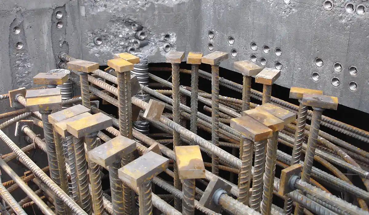
Historically bonded straight or hooked rebars were used to provide rebar anchorage. This method of anchoring reinforcement in concrete assumes sufficient bond between the rebar and the concrete. However, straight or hooked rebar may not provide the most effective anchorage and there are a few situations where headed bars may provide a desirable solution. When such headed bars are used, the required anchorage is achieved through bearing on the head or a combination of rebar bond and bearing on rebar deformations (see Fig.1)
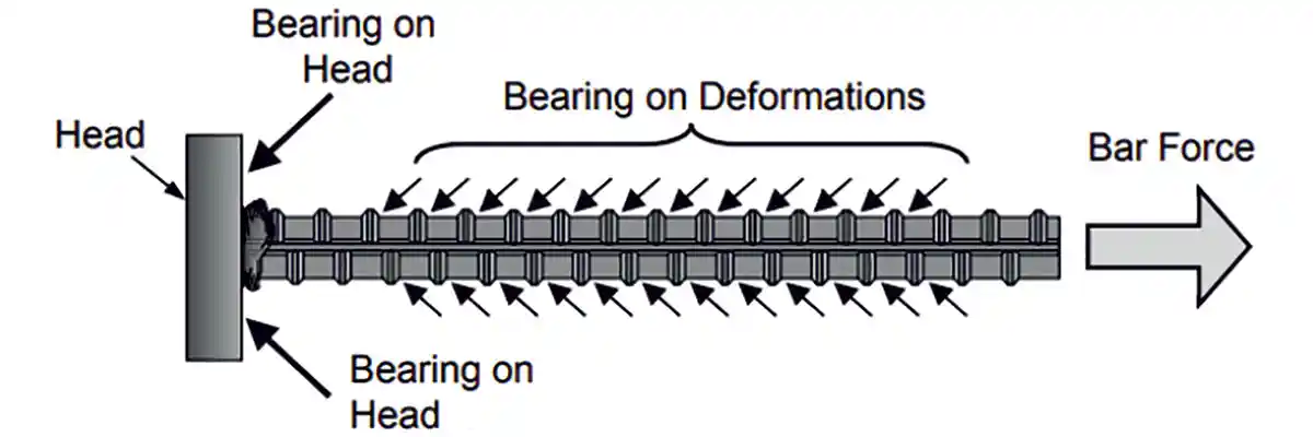 Figure 1: Anchorage achieved through bearing on head and a combination of rebar bond and bearing on rebar deformations (Source: Thompson et al., 2002)
The use of hooks often results in steel congestion, difficult fabrication and construction, and greater potential for poor concrete placement. In addition, cyclic loading tends to degrade the anchorage capacity due to the slip. The use of anchor plates or heads either welded or threaded to the longitudinal bar (often called headed bars) has been identified as a viable alternative to hooked bars in a variety of applications such as beam-column joints, knee joints, pile caps, column-roof slab connections, anchor cantilever beams, dapped end beams, corbels, transverse shear reinforcements, and shear wall cross ties. They also provide a number of advantages like ease of fabrication, construction, and concrete placement.
History of Headed Bars
Headed reinforcing bars have evolved from headed stud anchors. Studies on stud anchors began during 1960’s by the Nelson Stud Welding Company at Lehigh University (McMackin et al., 1973). Subsequently shear studs were found to be useful as punching shear reinforcement in flat slabs, based on the work by Dilger and Ghali at the University of Calgary, Canada (Dilger and Ghali, 1981 and Mokhtar et al., 1985). They found that closed stirrups are structurally deficient as punching shear reinforcement and difficult to construct, and hence suggested double-headed shear studs as an alternate solution. They recommended a head size of 10 times the bar area is necessary for proper anchorage of the studs. Based on these recommendations, the company Decon patented and commercially produced stud-rails with larger head areas in 1989.
Caltrans in USA also performed a study of headed reinforcement in the 1970’s, in order to anchor large diameter bars connecting bridge piers and box-girder superstructures (Stoker et al., 1974). The Alaska Oil and Gas Association (AOGA) was interested in the 1980’s to use double-headed bars as shear reinforcement in heavily reinforced concrete offshore oil platforms, who conducted several series of tests. Although the results of these tests are proprietary, some of them have been reported by Berner et al. (1991).
A friction-welded headed bar was developed, based on the work performed by Norwegian Contractors, Metalock and SINTEF (Thompson et al., 2002). This bar design has already been used extensively in several offshore and coastal structures. Some of them include: Oseburg Platform A, Gullfaks Platform C, the Ekofisk Barrier Wall, and Sleipner Platform A (both the original and revised designs), all of which are located in the North Sea (Berner and Hoff, 1994). Metalock patented the friction-welding technology and produced and started to sell friction-welded headed bars in the USA, under the banner of Headed Reinforcement Corporation (HRC).
At the same time, ERICO developed a threaded headed bar and marketed it in Europe during the 1980’s (Thompson et al., 2002). In the 1990’s, after its use in the offshore industry was successful, ERICO began to sell this product in the US market, under the trademark Lenton Terminator. Their headed bars had a smaller head than the products of HRC and Decon, with heads having only 4 times the bar area rather than 10 (Thompson et al., 2002). ERICO and HRC now support headed bar research focused primarily on bridge and seismic related applications. An extensive research was sponsored by HRC at the University of Texas at Austin and conducted by three Ph.D. students: DeVries, Bashandy, and Thompson (Bashandy, 1996, DeVries, 1996, DeVries, et al.,1999, and Thompson, 2002). They explored many of the potential applications and proposed anchorage provisions, and some of these provisions have been included in the ACI 318 Building Code (Thompson et al., 2002). Marchetto (2015), Alrasyid, et al. (2017), Lequesne (2018), and Wright and McCabe (1997) provide more literature review on headed bars.
Manufacturers and Standards of Headed bars
As mentioned earlier, HRC and ERICO are the first manufacturers of the headed bar. HRC produced friction-welded heads and provided four types of heads: square, rectangular, circular, and oval. ERICO produced a tapered thread connection between the reinforcing bar and the head, which when screwed provided a headed bar. Other firms such as Dextra Group, Bar Splice, and Dayton are also manufacturing similar types of headed bars.
Many headed deformed bar manufacturers offer products made from a variety of stainless steel alloys also. Headed deformed bars are also offered in epoxy and galvanic coatings. These coatings typically conform to the same coating standards as the reinforcing bar coatings (ASTM A775, A934, and A767).
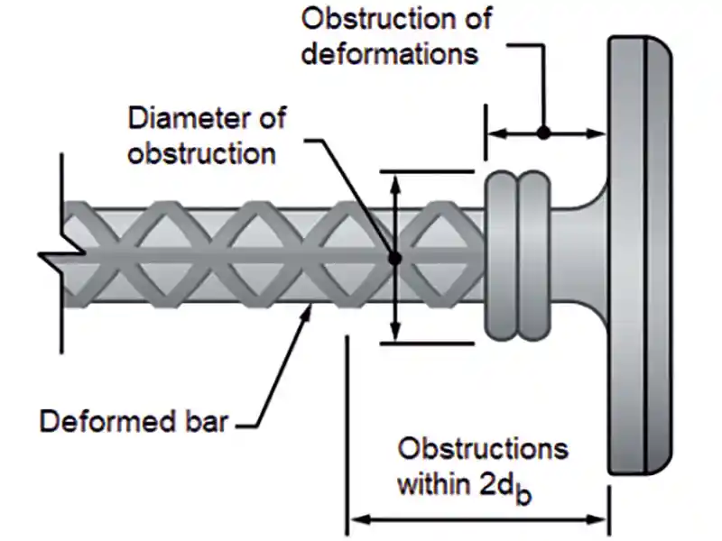 Figure 2: Obstruction limits for Class HA heads, as per ASTM A970 (Source: CRSI, 2014)
Both the IBC and ACI 318-19 require headed bars to meet the Class HA head requirements of Annex A1 of ASTM A970. These requirements are as below:
Figure 2: Obstruction limits for Class HA heads, as per ASTM A970 (Source: CRSI, 2014)
Both the IBC and ACI 318-19 require headed bars to meet the Class HA head requirements of Annex A1 of ASTM A970. These requirements are as below:
Headed bars with rectangular, round, or elliptical heads are available. The heads may be welded, forged, or threaded (Fig. 3).
Welded Heads: In this type, the head is welded to the reinforcing bar either through stick welding or friction welding. For head attachment method, A970 limits its use to ASTM A706 reinforcement.
Forged Heads: In this type, the head is produced by integrally hot-forging the head from the bar itself. For this method of head attachment, A970 permits either ASTM A706 or A615 reinforcing bars.
Threaded Heads: In this type, the head is attached to the rebar using taper or straight threads (internal to the head) or by a separate internally threaded nut and counter nut (see Fig.3(c)). For threaded heads, A970 permits either ASTM A615 or A706 reinforcing bars to be used.
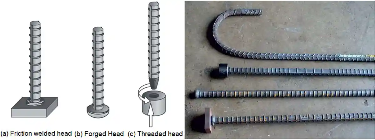 Figure 3: Types of heads: (a) Friction welded head, (b) Forged head, (c) Threaded head, (d) Various types of headed bars with a standard hook (25 mm diameter) (Source: Thompson et al., 2002)
Advantages of Using Headed Bars
The advantages of using headed bars are particularly evident when used in heavily reinforced concrete sections, where rebar congestion results in constructability problems. Hence, they are being used increasingly in civil infrastructure projects, nuclear power plants, and multi-storey buildings, where reinforcement congestion normally occurs.
The advantages of headed bars over reinforcing bars with a standard hook are:
Most manufacturers of headed bars produce products with two sizes -4Ab and 9Ab- of heads (Goodman, 2022). The smaller 4Ab head will have a net bearing area of at least four times the cross-sectional area of rebars, complying with ACI 318-19 and ASTM A970 requirements (The net bearing area equals the area of the head minus the nominal area of the bar (Abrg = Ahead – Ab). In this case, the anchorage is provided through a combination of bond (development length) and bearing. This small size head is used to terminate reinforcing bars in lieu of a standard hook (replacing standard hooks), which will improve constructability and reduce congestion. In most cases, the installation parameters for the headed bar are the same as that of the hooked bar they are replacing. It has to be noted that ACI 318-19 code does allow for a shorter development length when using headed bars.
The larger 9Ab heads will have a net bearing area of nine times the cross-sectional area of rebars (this was the standard in the USA prior to 2004 and the standard head in Europe and Canada now. It has a gross bearing area (including the area of bar > 10 Ab). Caltrans in the USA approved the use of full-size (9Ab) headed bars for bridges. It is important to note that the 9Ab head is bond-independent (no development length required). The anchorage in this case is provided through bearing alone directly beneath the head. The 9Ab heads are used to terminate reinforcing bars when the point of maximum stress is close to the end of the bar or when the development length leading up to the head is neglected during design.
As mentioned already, headed bar reinforcement is usually formed by friction welding of plates, by forging an upset bearing surface at the end of a reinforcing bar, or by forging threads into the end of the bar, which are then used to attach the plate. Headed bar reinforcement must comply with ASTM A970/A970M-18 requirements, which include tensile tests that confirm that necking occurs at least one diameter away from the head. Headed bar reinforcement must be made of A706-Grade 60 steel and meets the stress and strain requirements of Caltrans Seismic Design Criteria (SDC).
The Behavior of Headed Bars
Thompson et al. (2006) suggested that the headed bar anchorage is provided by a combination of head bearing and bond. The initial anchorage is provided by the bond between the concrete and rebar. As additional load is applied to the bar, the bond achieves peak capacity and begins to decline. As the process of bond deterioration occurs, the bond anchorage is transferred to the head, causing a rise in the head bearing. The anchorage capacity at failure is provided by a combination of peak head bearing and reduced bond. Thompson et al. (2006) opinioned that strut-and-tie models are the best for determining the anchorage length and that the node and strut dimensions play a critical role in defining the anchorage length. They also recommended a minimum anchorage length of 6db.
Tests conducted by Chun et al. (2007) and Kang et al. (2010) reveal that the hysteretic behaviour of exterior joints constructed with headed bars was similar to or even superior to joints with hooked bars. Head size with a net area of four times the bar area was sufficient to anchor the beam reinforcement effectively (with a development length shorter than that needed for hooked bars) within the exterior beam-column joint. For roof-level connections, anchoring the column heads above the beam bars and adding an additional layer of transverse reinforcement led to improved behavior.
Development Length of Headed Bars
As per ACI 318-19, the headed bar should comply with the provisions of ASTM A970. However, in Europe, the ISO 15698 is followed. In India, IS 456, IRC 112 as well as the design guide SP 34 allow the use of headed bars. It has to be noted that the IRC 112 provisions are similar to the Eurocode 2 provisions. Though the IS 456:2000 states that mechanical devices can be used to anchor bars with the approval of the engineer-in-charge, it does not contain any clause to calculate the anchorage length. Clause 25.4.4.2 of the ACI 318-19 code suggests Eqn. 1 to determine the development length of headed deformed bars in tension, Ldt (see Fig. 4).
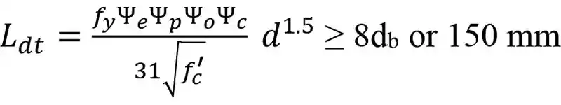 (1)
Where, Ldt = development length in tension of headed deformed bar, measured from the critical section to the bearing (inside) face of the head, (mm), ѱe, ѱp, ѱo, and ѱc are factors used to modify development length based on reinforcement coating, parallel tie reinforcement, side cover and confinement, and concrete strength, respectively ( ѱe = 1.2 for epoxy-coated bars = 1.0 for uncoated or zinc-coated bars- values of other modification factors are given in Table 25.4.4.3 of ACI 318-19), fy = specified yield strength of the reinforcing bar (MPa), fc’ = specified compressive cylinder strength of concrete (MPa) ≤ 40 MPa, and db = nominal diameter of the bar (mm). Note that Eqn. 1 results in a development length of approximately 80% of that required for hooked bars. Also Eqn. 1 is not a function of the head size, though it is indirectly accounted for the minimum requirements.
(1)
Where, Ldt = development length in tension of headed deformed bar, measured from the critical section to the bearing (inside) face of the head, (mm), ѱe, ѱp, ѱo, and ѱc are factors used to modify development length based on reinforcement coating, parallel tie reinforcement, side cover and confinement, and concrete strength, respectively ( ѱe = 1.2 for epoxy-coated bars = 1.0 for uncoated or zinc-coated bars- values of other modification factors are given in Table 25.4.4.3 of ACI 318-19), fy = specified yield strength of the reinforcing bar (MPa), fc’ = specified compressive cylinder strength of concrete (MPa) ≤ 40 MPa, and db = nominal diameter of the bar (mm). Note that Eqn. 1 results in a development length of approximately 80% of that required for hooked bars. Also Eqn. 1 is not a function of the head size, though it is indirectly accounted for the minimum requirements.
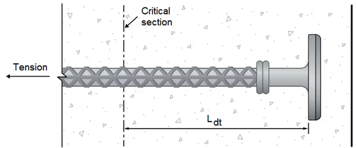 Figure 4: Development length of headed deformed bars (Source: CRSI, 2014)
ACI 318-19 required that the headed bar should satisfy the following: (1) The yielding strength of bar should not exceed 420 MPa; (2) The maximum bar diameter should be ≤ 36mm; (3) The net bearing area should be at least 4Ab, where Ab is the area of bar; (4) Clear cover of the bar should not be less than 2db, (5) Clear spacing between bars should not be less than 4db, and (6) Normal weight concrete is used. The above restrictions are based on the available experimental results (Thompson et al., 2006, Shao, et al., 2016). CRSI (2014) suggests that when measuring cover, the measurement is taken from the edge of concrete to the bar, not to the head. However, it is better to take the cover from the edge of concrete to the head. Similarly, as per CRSI (2014), the spacing is measured from the inner edge of each bar, and not to the reinforcing bar centerline or the head.
In a recent paper, Sim and Chun (2022) investigated the side-face blowout strength of headed bars in high-strength concrete. Based on the tests of thirty-two simulated exterior beam-column joints with concrete of grade 80 and 120 MPa, they developed the following equation for the development length of the headed bar.
 (2a)
(2a)
(2b)
Where, cso is the clear cover, and Ktr is the transverse reinforcement index = 40 Atr /sn, Atr = total area of transverse reinforcement within the spacing, s, that crosses the plane of splitting through the reinforcement being developed, mm2, s = maximum spacing of transverse reinforcement within Ld, center-to-center (mm), and n = number of bars being developed along the plane of splitting. Sim and Chun (2022) suggest that the above equation is valid when fc’ ≤120 MPa; 1.0 ≤ cso/db ≤3.0; Ktr/db ≤0.7. The average of the test-to-prediction ratio using Eqn.(2) was found to be 1.01 with a coefficient of variation (COV) of 10.8%.
To avoid congestion, it may be desirable to stagger the heads of these bars. When longitudinal headed bars from a beam terminate at a supporting column, the bars should be extended up to the far face of the confined core of the column, as shown in Fig. 5 (allowing for the cover and avoiding interference with column reinforcement). Extending the bar to the far side of the column core helps engage the entire joint in resisting the anchorage forces and thereby improves the performance of the joint (ACI 318-19). Due to this, the anchorage length may exceed Ldt. However, the anchorage strength is found to be higher, if the anchorage length is ≥ d/1.5, as shown in Fig. 5(b) (Eligehausen, 2006), or by providing reinforcement in the form of hoops and ties to establish a load path in accordance with strut-and-tie modeling. Thompson et al. (2006) also cautioned that the location of the critical section based on the strut-and-tie model will be different from the one assumed based on beam theory. Also, as per ACI 318-19, headed bars should not be considered effective in compression, as no test data are available yet to show that the use of heads is beneficial in compression.
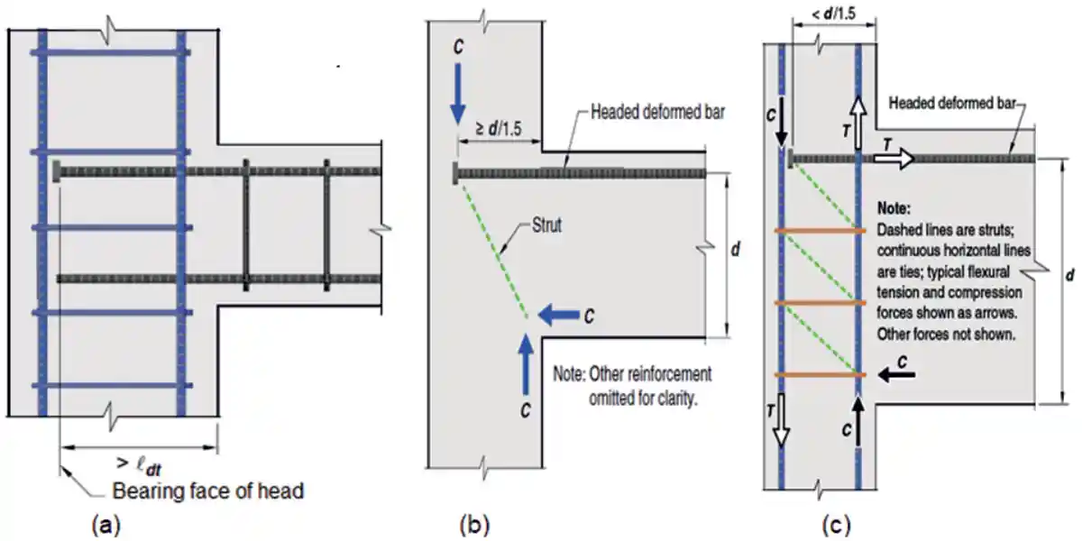 Figure 5 (a): Headed deformed bar extended to the far side of column core, (b) Breakout failure can be avoided if the anchorage length is ≥ d/1.5 (c) Horizontal reinforcement in the joint can also prevent breakout failure, enabling strut-and-tie mechanism (source: ACI 318-19).
Recently, Chourasia et al. (2023) conducted extensive experimental and numerical investigations on RC beam-column joints with plain and deformed (grooved and ribbed) headed bars and compared their performance with conventional rebars and development length. The grooved and ribbed heads adopted by them is shown in Fig. 6. The numerical and experimental investigations done by them showed that the grooved-headed and ribbed-headed bars exhibited superior cyclic load resistance in comparison to plain-headed bar specimens (an average of 4.39% and 26.56% increase in loading capacity). Head deformations improved the bond between the concrete and head owing to mechanical interlocking, which consequently prevented slip of bar and delayed failure. They also found that the joints with steel fibers lead to an overall enhancement of load-carrying capacity in the range of 25%–40%, as well as higher stiffness as compared with the specimens without steel fibers.
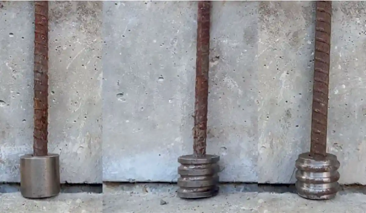 Figure 6: Plain, grooved, and ribbed type headed bars investigated by Chourasia et al. (2023)
The Uses and Application of Headed Bars
As discussed earlier, the most common applications for headed deformed bars are to provide anchorage to terminate a reinforcing bar, replace standard hooks, or shear reinforcement. In addition, they can also be used as confinement reinforcement. Headed bars can be used in a variety of applications which may include beam-column joints, knee joints, pile caps, column-roof slab connections, anchor cantilever beams, dapped end beams, corbels, transverse shear reinforcements, and shear wall cross ties.
 Their above uses are detailed as below:
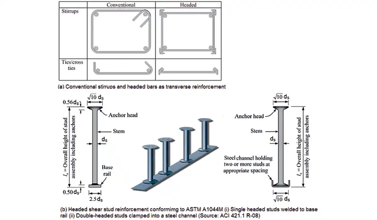 Figure 10: Use of headed bars as shear and punching shear reinforcement
Summary And Conclusions
Rebar congestion can result in labour intensive site fabrication and lead to reduction in performance of concrete sections. The use of headed bars in such situations, help to reduce rebar congestion, facilitating better concrete consolidation and making easy the rebar fabrication and handling at site, compared to the traditional bent bar anchorages. Thus, the use of headed rebars offers time and cost advantages, in addition to improvements in the quality of concrete. Headed bars with rectangular, round, or elliptical heads are available. Headed bar reinforcement is usually formed by friction welding of plates, forging an upset bearing surface at the end of a reinforcing bar, or forging threads into the end of the bar, which are then used to attach the plate. Most manufacturers of headed bars produce products with two sizes of heads - 4Ab and 9Ab. In the case of heads with 4Ab size, the anchorage is provided through a combination of bond and bearing. Whereas, the 9Ab head size may provide the required anchorage through bearing, and hence may not require any development length.
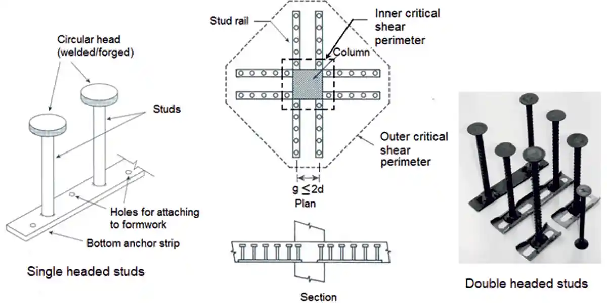 Figure 11: Headed studs as punching reinforcement-Typical arrangement (Adapted from ACI 318:19)
Strut-and-tie models can be used to determine the anchorage length; the node and strut dimensions play a critical role in defining the anchorage length. A minimum anchorage length of 6 to 8db is often specified. The headed bar should comply with the provisions of ASTM A970. ACI 318:19 provides an equation to determine the development length of headed bars, with modification factors to take into account reinforcement coating, parallel tie reinforcement, side cover and confinement, and concrete strength. Grooved-headed and ribbed-headed bars may exhibit superior cyclic load resistance as compared to plain-headed bars. Headed bars can be used advantageously in a variety of applications, including beam-column joints, knee joints, pile caps, column-roof slab connections, anchor cantilever beams, dapped end beams, corbels, transverse shear reinforcements, and shear wall cross ties.
References
 Figure 12: Use of Headed bars in Corbels (source: Yang et al., 2010)
ACI 318-19, Building Code Requirements for Structural Concrete and Commentary, American Concrete Institute, Farmington Hills, Michigan, 628 pp.
Figure 12: Use of Headed bars in Corbels (source: Yang et al., 2010)
ACI 318-19, Building Code Requirements for Structural Concrete and Commentary, American Concrete Institute, Farmington Hills, Michigan, 628 pp.
ACI 421.1 R-20 Guide to Shear Reinforcement for Slabs, American Concrete Institute, Farmington Hills, Michigan, 32 pp.
Alrasyid, H., Yoganata, Y.S., Suluch, M. and Iranata, D.(2017) “Headed Reinforcement in Concrete Structure: State of The Art”, 3rd International Conference on Construction and Building Engineering, AIP Conference Proceedings 1903,020015. https://doi.org/10.1063/1.5011495
ASTM A970/A970M-18, “Standard Specification for Headed Steel Bars for Concrete Reinforcement,” West Conshohocken, PA, 2018, 10 pp.
Bashandy, T.R. (1996) Application of Headed Bars in Concrete Members, Ph.D. thesis, The University of Texas at Austin.
Berner, D.E., Gerwick, B.C., and Hoff, G.C. (1991) “T-Headed Stirrup Bars,” Concrete International, ACI, Vol. 13, No. 5, pp.
Berner, D.E. and Hoff, G.C. (1994) “Headed Reinforcement in Disturbed Strain Regions of Concrete Members,” Concrete International, Vol. 16, No. 1, Jan.
Chourasia, A., Singhal, S., Parashar, J., Chourasia, A. (2023) “Reinforced concrete and beam-columns anchored with headed bars subjected to reversed cyclic loading: Experimental and numerical investigation”, Structural Concrete, pp.1-15. https://doi.org/10.1002/suco.202100468
Chun S-C., Lee, S-H., Kang, T.H.-K, Oh, B., and Wallace, J.W. (2007) “Mechanical anchorage in exterior beam-column joints subjected to cyclic loading”, ACI Structural Journal, Vol. 104, No. 1, pp. 102–112.
CRSI (2014), “Frequently Asked Questions (FAQ) About Headed Reinforcing Bars”, CRSI Technical Note ETN-M-3-14, Concrete Reinforcing Steel Institute, Schaumburg, Illinois, 8 pp.
DeVries, R.A. (1996) Anchorage of Headed Reinforcement in Concrete. Ph.D. thesis, The University of Texas at Austin.
Devries, R.A., Jirsa, J.O., and Bashandy, T. (1999) “Anchorage Capacity in Concrete of Headed Reinforcement with Shallow Embedments” ACI Structural Journal, Vol. 96, No. 5, pp. 728-737.
Dilger, W. H., and A. Ghali (1981) “Shear Reinforcement for Concrete Slabs”, Journal of the Structural Div., ASCE, Vol. 107, ST 12, Dec., pp. 2403 -2420.
Eligehausen, R., Mallée, R., and Silva, J. (2006) Anchorage in Concrete Construction, Ernst & Sohn, Berlin, Germany, May, 380 p.
Elgabry, A.E., and A. Ghali, Design of stud-shear reinforcement for slabs, ACI Structural Journal, Vol. 87, No. 3, May-June 1990, pp. 350-361.
Ghali, A., and W.H. Dilger (1998) “Anchoring with double headed studs”, Concrete International, ACI, Vol. 20, No. 11, Nov., pp.21-24.
Ghali, A., and N. Hammill (1992), Effectiveness of shear reinforcement in slabs, Concrete International, ACI, Vol. 14, No. 2, Feb., pp. 60-65.
Ghali A., and S.A. Youakim (2005) “Headed studs in concrete: state of the art”, ACI Structural Journal, Vol. 102, No. 5, Sept.-Oct., pp. 657–667.
Goodman, R. (2022) “Use of Headed Bars in Reinforced Concrete Design”, NBM & CW, July,
Kang, T.H.-K, Ha, S.-S. and Choi D.-U. (2010) “Bar pullout tests and seismic tests of small-headed bars in beam-column joints”, ACI Structural Journal, Vol. 107, No. 1, pp. 32–42.
Lequesne, R.D., O’Reilly, M., Darwin, D., Lepage, A., Al-Sabawy, A., Guillen, E., and Spradling, D. (2018) Use of Headed Bars as Shear Reinforcement, SM Report No.126, The University of Kansas Center for Research, Inc., Lawrence, Kansas, 265 pp.
Marchetto, F.(2015) Use of Headed Reinforcement Bars in Construction, Ph.D. Thesis, Department Of Continuum Mechanics and Theory of Structures, School Of Civil Engineering, Technical University Of Madrid, 355 pp. https://oa.upm.es/36378/1/FRANCESCO_MARCHETTO.pdf
McMackin P.J., Slutter R.G., and Fisher J.W. (1973) “Headed steel anchor under combined loading”, Engineering Journal, AISC, Vol. 10, 2nd Quarter, pp. 43–52.
Mokhtar, A.S., Ghali, A., and Dilger, W.H. (1985), “Stud Shear Reinforcement for Flat Concrete Plates,” Journal of the American Concrete Institute, Proc., Vol. 82, No. 5, Sept.-Oct., pp. 676-683.
Shao, Y.; Darwin, D.; O’Reilly, M.; Lequesne, R. D.; Ghimire, K.; and Hano, M. (2016), Anchorage of Conventional and High-Strength Headed Reinforcing Bars, SM Report No. 117, University of Kansas Center for Research, Lawrence, KS, 234 pp. https://kuscholarworks.ku.edu/ handle/1808/21738
Shen, Li, B., Chen, Y.-T., and Tizani, W. (2021) “Seismic Performance Of RC Interior Beam-Column Joints With Novel Reinforcement Detail”, Engineering Structures, Vol. 227, 111408, 13 pp.
Sim, H.-J., and Chun, S.-C. (2022) “Side-Face Blowout Failure Of Headed Bars In High-Strength Concrete”, ACI Structural Journal, Vol. 119, No. 5, Sept., pp. 3-16.
Stoker, J.R., Boulware, R.L., Crozier, W.F., and Swirsky, R.A. (1974) “Anchorage Devices for Large Diameter Reinforcing Bars,” Report No. CA-DOT-TL-6626-1-73-30, California Department of Transportation, Sacramento, California.
Subramanian, N. (2013) Design of Reinforced Concrete Structures, Oxford University Press, New Delhi, 880 pp.
Thompson, M.K. (2002) The Anchorage Behavior of Headed Reinforcement in CCT Nodes and Lap Splices, PhD Thesis, The University of Texas at Austin.
Thompson, M.K., Jirsa, O.J., and Breen, J.E. and Klingner, R.E. (2002) Anchorage Behavior of Headed Reinforcement: Literature Review, Research report FHWA/TX-0-1855-1, Center For Transportation Research, Bureau of Engineering Research, The University of Texas at Austin, 102 pp.
Thompson, M.K., Jirsa, O.J., and Breen, J.E. (2006) “CCT nodes anchored by headed bars- Part 2: capacity of nodes”, ACI Structural Journal, Vol. 103, No. 1, pp. 65-73.
Thompson, M.K., Jirsa, O.J., and Breen, J.E. (2006) “Behavior and Capacity of Headed Reinforcement”, ACI Structural Journal, Vol.103, No. 4, July-Aug., pp.522-530.
Thompson, M. K., Ledesma, A., Jirsa, O.J., and Breen, J.E. (2006) “Lap splices anchored by headed bars”, ACI Structural Journal, Vol. 103, No. 2, Mar.-Apr. 2006, pp. 271-279.
Yang, J.M., Min, K.H., Shin, H.O., and Y.S. Yoon (2010) “The use of T-headed bars in high-strength concrete members”, Conf. on Fracture Mechanics of Concrete and Concrete Structures-High Performance, Fiber Reinforced Concrete, Special Loadings and Structural Applications, May 23-28, B. H. Oh, et al. (eds.), Korea Concrete Institute, pp.1328-1334
Wright, J.L. and McCabe, S.L. (1997) The development length and anchorage behavior of headed reinforcing bars, SM Report 44, University of Kansas Center for Research, Lawrence, Kansas.
About the Author
 Dr. N. Subramanian, Ph.D., FNAE, an award-winning author, consultant, and mentor, now living in Maryland, USA, is the former chief executive of Computer Design Consultants, India. A doctorate from IITM, he has also worked with the TU Berlin and the University of Bundeswehr, Munich for 2 years as Alexander von Humboldt Fellow. He has 45 years of professional experience which includes consultancy, research, and teaching in India and abroad. Dr. Subramanian has authored 25 books and 300 technical papers and served as a past vice president of ICI and the ACCE (I). He is a recipient of several awards including the ICI - L&T Life-Time Achievement award of the ICI (2013), Tamil Nadu scientist award (2001), Gourav Award of the ACCE(I) (2021), and the ACCE(I)-Nagadi best book award for three of his books (2000,2011,2013). He has also been in the Editorial Board/Review committee of several Indian and international journals.
Dr. N. Subramanian, Ph.D., FNAE
Headed bars: An alternative to hooked bars
Headed bars may provide a desirable alternative to hooked bars from the consideration of design as well as constructability. They are available with rectangular, round, or elliptical heads and the heads may be formed by friction welding of plates, forging an upset bearing surface at the end of a reinforcing bar, or forging threads into the end of the bar, which are then used to attach the plate.
The use of headed bars instead of hooked bars offer several advantages like requirement of reduced development length, reduced congestion, ease of transport and fixing at site, better concrete consolidation, and better performance under seismic loads. The heads of 4Ab size provides anchorage through a combination of bond and bearing, whereas the heads of 9Ab size provides anchorage only through bearing. ACI 318-19 provided an equation to determine the development length of headed bars. Headed bars can be used advantageously in a variety of applications, including beam-column joints, knee joints, pile caps, column-roof slab connections, anchor cantilever beams, dapped end beams, corbels, transverse shear reinforcements, and shear wall cross ties.
Introduction
Historically bonded straight or hooked rebars were used to provide rebar anchorage. This method of anchoring reinforcement in concrete assumes sufficient bond between the rebar and the concrete. However, straight or hooked rebar may not provide the most effective anchorage and there are a few situations where headed bars may provide a desirable solution. When such headed bars are used, the required anchorage is achieved through bearing on the head or a combination of rebar bond and bearing on rebar deformations (see Fig.1)
Figure 1: Anchorage achieved through bearing on head and a combination of rebar bond and bearing on rebar deformations (Source: Thompson et al., 2002)The use of hooks often results in steel congestion, difficult fabrication and construction, and greater potential for poor concrete placement. In addition, cyclic loading tends to degrade the anchorage capacity due to the slip. The use of anchor plates or heads either welded or threaded to the longitudinal bar (often called headed bars) has been identified as a viable alternative to hooked bars in a variety of applications such as beam-column joints, knee joints, pile caps, column-roof slab connections, anchor cantilever beams, dapped end beams, corbels, transverse shear reinforcements, and shear wall cross ties. They also provide a number of advantages like ease of fabrication, construction, and concrete placement.
History of Headed Bars
Headed reinforcing bars have evolved from headed stud anchors. Studies on stud anchors began during 1960’s by the Nelson Stud Welding Company at Lehigh University (McMackin et al., 1973). Subsequently shear studs were found to be useful as punching shear reinforcement in flat slabs, based on the work by Dilger and Ghali at the University of Calgary, Canada (Dilger and Ghali, 1981 and Mokhtar et al., 1985). They found that closed stirrups are structurally deficient as punching shear reinforcement and difficult to construct, and hence suggested double-headed shear studs as an alternate solution. They recommended a head size of 10 times the bar area is necessary for proper anchorage of the studs. Based on these recommendations, the company Decon patented and commercially produced stud-rails with larger head areas in 1989.
Caltrans in USA also performed a study of headed reinforcement in the 1970’s, in order to anchor large diameter bars connecting bridge piers and box-girder superstructures (Stoker et al., 1974). The Alaska Oil and Gas Association (AOGA) was interested in the 1980’s to use double-headed bars as shear reinforcement in heavily reinforced concrete offshore oil platforms, who conducted several series of tests. Although the results of these tests are proprietary, some of them have been reported by Berner et al. (1991).
A friction-welded headed bar was developed, based on the work performed by Norwegian Contractors, Metalock and SINTEF (Thompson et al., 2002). This bar design has already been used extensively in several offshore and coastal structures. Some of them include: Oseburg Platform A, Gullfaks Platform C, the Ekofisk Barrier Wall, and Sleipner Platform A (both the original and revised designs), all of which are located in the North Sea (Berner and Hoff, 1994). Metalock patented the friction-welding technology and produced and started to sell friction-welded headed bars in the USA, under the banner of Headed Reinforcement Corporation (HRC).
At the same time, ERICO developed a threaded headed bar and marketed it in Europe during the 1980’s (Thompson et al., 2002). In the 1990’s, after its use in the offshore industry was successful, ERICO began to sell this product in the US market, under the trademark Lenton Terminator. Their headed bars had a smaller head than the products of HRC and Decon, with heads having only 4 times the bar area rather than 10 (Thompson et al., 2002). ERICO and HRC now support headed bar research focused primarily on bridge and seismic related applications. An extensive research was sponsored by HRC at the University of Texas at Austin and conducted by three Ph.D. students: DeVries, Bashandy, and Thompson (Bashandy, 1996, DeVries, 1996, DeVries, et al.,1999, and Thompson, 2002). They explored many of the potential applications and proposed anchorage provisions, and some of these provisions have been included in the ACI 318 Building Code (Thompson et al., 2002). Marchetto (2015), Alrasyid, et al. (2017), Lequesne (2018), and Wright and McCabe (1997) provide more literature review on headed bars.
Manufacturers and Standards of Headed bars
As mentioned earlier, HRC and ERICO are the first manufacturers of the headed bar. HRC produced friction-welded heads and provided four types of heads: square, rectangular, circular, and oval. ERICO produced a tapered thread connection between the reinforcing bar and the head, which when screwed provided a headed bar. Other firms such as Dextra Group, Bar Splice, and Dayton are also manufacturing similar types of headed bars.
Many headed deformed bar manufacturers offer products made from a variety of stainless steel alloys also. Headed deformed bars are also offered in epoxy and galvanic coatings. These coatings typically conform to the same coating standards as the reinforcing bar coatings (ASTM A775, A934, and A767).
Figure 2: Obstruction limits for Class HA heads, as per ASTM A970 (Source: CRSI, 2014)- Class HA heads must have a net bearing area of at least 4 times the area of the bar, Ab (Abrg ≥ 4Ab). The net bearing area will be the area of the head minus area of the bar (Abrg = Ahead - Ab). The bearing area has to be a single, nominally flat surface perpendicular to the longitudinal axis of the bar.
- Class HA heads must not have obstructions in the deformation pattern in front of the head greater than 2db, (where db is the nominal diameter of bar) along the axis of the bar. The obstructions must not have a diameter greater than 1.5db, as shown in Fig 2.
- Class HA heads must develop the minimum specified tensile strength of the bar.
- Class HA heads must be marked with a letter “H” to indicate it was produced in conformance with Annex A1 of ASTM A970.
Headed bars with rectangular, round, or elliptical heads are available. The heads may be welded, forged, or threaded (Fig. 3).
Welded Heads: In this type, the head is welded to the reinforcing bar either through stick welding or friction welding. For head attachment method, A970 limits its use to ASTM A706 reinforcement.
Forged Heads: In this type, the head is produced by integrally hot-forging the head from the bar itself. For this method of head attachment, A970 permits either ASTM A706 or A615 reinforcing bars.
Threaded Heads: In this type, the head is attached to the rebar using taper or straight threads (internal to the head) or by a separate internally threaded nut and counter nut (see Fig.3(c)). For threaded heads, A970 permits either ASTM A615 or A706 reinforcing bars to be used.
Figure 3: Types of heads: (a) Friction welded head, (b) Forged head, (c) Threaded head, (d) Various types of headed bars with a standard hook (25 mm diameter) (Source: Thompson et al., 2002) Advantages of Using Headed Bars
The advantages of using headed bars are particularly evident when used in heavily reinforced concrete sections, where rebar congestion results in constructability problems. Hence, they are being used increasingly in civil infrastructure projects, nuclear power plants, and multi-storey buildings, where reinforcement congestion normally occurs.
The advantages of headed bars over reinforcing bars with a standard hook are:
- The use of headed bars eliminates the requirement of bending the bars for satisfying anchorage length and also allows the reduction in tension development length.
- The use of headed bars results in reduced congestion, ease of placement, and better concrete consolidation. Such reduction of congestion will also result in better behavior under seismic loads.
- It is easier to insert the longitudinal bar in a cage during construction. Longitudinal bars with a hook protruding at one or both ends can make insertion of the hooked bar into a reinforcing bar cage difficult, especially if there are bars transverse to the hooked bar.
- Since headed bars do not protrude as much as hooks there is less impact on cover constraints.
- The transportation of straight lengths of rebars with headed ends is easier than transporting rebars with bent anchorages.
- The on-site handling and fixing also become easier. Thus, the use of headed bars can offer considerable time and cost advantages as well as potential improvement in the quality of concrete. The head can be screwed or unscrewed to suit any adjustment if needed.
Most manufacturers of headed bars produce products with two sizes -4Ab and 9Ab- of heads (Goodman, 2022). The smaller 4Ab head will have a net bearing area of at least four times the cross-sectional area of rebars, complying with ACI 318-19 and ASTM A970 requirements (The net bearing area equals the area of the head minus the nominal area of the bar (Abrg = Ahead – Ab). In this case, the anchorage is provided through a combination of bond (development length) and bearing. This small size head is used to terminate reinforcing bars in lieu of a standard hook (replacing standard hooks), which will improve constructability and reduce congestion. In most cases, the installation parameters for the headed bar are the same as that of the hooked bar they are replacing. It has to be noted that ACI 318-19 code does allow for a shorter development length when using headed bars.
The larger 9Ab heads will have a net bearing area of nine times the cross-sectional area of rebars (this was the standard in the USA prior to 2004 and the standard head in Europe and Canada now. It has a gross bearing area (including the area of bar > 10 Ab). Caltrans in the USA approved the use of full-size (9Ab) headed bars for bridges. It is important to note that the 9Ab head is bond-independent (no development length required). The anchorage in this case is provided through bearing alone directly beneath the head. The 9Ab heads are used to terminate reinforcing bars when the point of maximum stress is close to the end of the bar or when the development length leading up to the head is neglected during design.
As mentioned already, headed bar reinforcement is usually formed by friction welding of plates, by forging an upset bearing surface at the end of a reinforcing bar, or by forging threads into the end of the bar, which are then used to attach the plate. Headed bar reinforcement must comply with ASTM A970/A970M-18 requirements, which include tensile tests that confirm that necking occurs at least one diameter away from the head. Headed bar reinforcement must be made of A706-Grade 60 steel and meets the stress and strain requirements of Caltrans Seismic Design Criteria (SDC).
The Behavior of Headed Bars
Thompson et al. (2006) suggested that the headed bar anchorage is provided by a combination of head bearing and bond. The initial anchorage is provided by the bond between the concrete and rebar. As additional load is applied to the bar, the bond achieves peak capacity and begins to decline. As the process of bond deterioration occurs, the bond anchorage is transferred to the head, causing a rise in the head bearing. The anchorage capacity at failure is provided by a combination of peak head bearing and reduced bond. Thompson et al. (2006) opinioned that strut-and-tie models are the best for determining the anchorage length and that the node and strut dimensions play a critical role in defining the anchorage length. They also recommended a minimum anchorage length of 6db.
Tests conducted by Chun et al. (2007) and Kang et al. (2010) reveal that the hysteretic behaviour of exterior joints constructed with headed bars was similar to or even superior to joints with hooked bars. Head size with a net area of four times the bar area was sufficient to anchor the beam reinforcement effectively (with a development length shorter than that needed for hooked bars) within the exterior beam-column joint. For roof-level connections, anchoring the column heads above the beam bars and adding an additional layer of transverse reinforcement led to improved behavior.
Development Length of Headed Bars
As per ACI 318-19, the headed bar should comply with the provisions of ASTM A970. However, in Europe, the ISO 15698 is followed. In India, IS 456, IRC 112 as well as the design guide SP 34 allow the use of headed bars. It has to be noted that the IRC 112 provisions are similar to the Eurocode 2 provisions. Though the IS 456:2000 states that mechanical devices can be used to anchor bars with the approval of the engineer-in-charge, it does not contain any clause to calculate the anchorage length. Clause 25.4.4.2 of the ACI 318-19 code suggests Eqn. 1 to determine the development length of headed deformed bars in tension, Ldt (see Fig. 4).
Figure 4: Development length of headed deformed bars (Source: CRSI, 2014)ACI 318-19 required that the headed bar should satisfy the following: (1) The yielding strength of bar should not exceed 420 MPa; (2) The maximum bar diameter should be ≤ 36mm; (3) The net bearing area should be at least 4Ab, where Ab is the area of bar; (4) Clear cover of the bar should not be less than 2db, (5) Clear spacing between bars should not be less than 4db, and (6) Normal weight concrete is used. The above restrictions are based on the available experimental results (Thompson et al., 2006, Shao, et al., 2016). CRSI (2014) suggests that when measuring cover, the measurement is taken from the edge of concrete to the bar, not to the head. However, it is better to take the cover from the edge of concrete to the head. Similarly, as per CRSI (2014), the spacing is measured from the inner edge of each bar, and not to the reinforcing bar centerline or the head.
In a recent paper, Sim and Chun (2022) investigated the side-face blowout strength of headed bars in high-strength concrete. Based on the tests of thirty-two simulated exterior beam-column joints with concrete of grade 80 and 120 MPa, they developed the following equation for the development length of the headed bar.
(2b)
Where, cso is the clear cover, and Ktr is the transverse reinforcement index = 40 Atr /sn, Atr = total area of transverse reinforcement within the spacing, s, that crosses the plane of splitting through the reinforcement being developed, mm2, s = maximum spacing of transverse reinforcement within Ld, center-to-center (mm), and n = number of bars being developed along the plane of splitting. Sim and Chun (2022) suggest that the above equation is valid when fc’ ≤120 MPa; 1.0 ≤ cso/db ≤3.0; Ktr/db ≤0.7. The average of the test-to-prediction ratio using Eqn.(2) was found to be 1.01 with a coefficient of variation (COV) of 10.8%.
To avoid congestion, it may be desirable to stagger the heads of these bars. When longitudinal headed bars from a beam terminate at a supporting column, the bars should be extended up to the far face of the confined core of the column, as shown in Fig. 5 (allowing for the cover and avoiding interference with column reinforcement). Extending the bar to the far side of the column core helps engage the entire joint in resisting the anchorage forces and thereby improves the performance of the joint (ACI 318-19). Due to this, the anchorage length may exceed Ldt. However, the anchorage strength is found to be higher, if the anchorage length is ≥ d/1.5, as shown in Fig. 5(b) (Eligehausen, 2006), or by providing reinforcement in the form of hoops and ties to establish a load path in accordance with strut-and-tie modeling. Thompson et al. (2006) also cautioned that the location of the critical section based on the strut-and-tie model will be different from the one assumed based on beam theory. Also, as per ACI 318-19, headed bars should not be considered effective in compression, as no test data are available yet to show that the use of heads is beneficial in compression.
Figure 5 (a): Headed deformed bar extended to the far side of column core, (b) Breakout failure can be avoided if the anchorage length is ≥ d/1.5 (c) Horizontal reinforcement in the joint can also prevent breakout failure, enabling strut-and-tie mechanism (source: ACI 318-19).Recently, Chourasia et al. (2023) conducted extensive experimental and numerical investigations on RC beam-column joints with plain and deformed (grooved and ribbed) headed bars and compared their performance with conventional rebars and development length. The grooved and ribbed heads adopted by them is shown in Fig. 6. The numerical and experimental investigations done by them showed that the grooved-headed and ribbed-headed bars exhibited superior cyclic load resistance in comparison to plain-headed bar specimens (an average of 4.39% and 26.56% increase in loading capacity). Head deformations improved the bond between the concrete and head owing to mechanical interlocking, which consequently prevented slip of bar and delayed failure. They also found that the joints with steel fibers lead to an overall enhancement of load-carrying capacity in the range of 25%–40%, as well as higher stiffness as compared with the specimens without steel fibers.
Figure 6: Plain, grooved, and ribbed type headed bars investigated by Chourasia et al. (2023)The Uses and Application of Headed Bars
As discussed earlier, the most common applications for headed deformed bars are to provide anchorage to terminate a reinforcing bar, replace standard hooks, or shear reinforcement. In addition, they can also be used as confinement reinforcement. Headed bars can be used in a variety of applications which may include beam-column joints, knee joints, pile caps, column-roof slab connections, anchor cantilever beams, dapped end beams, corbels, transverse shear reinforcements, and shear wall cross ties.
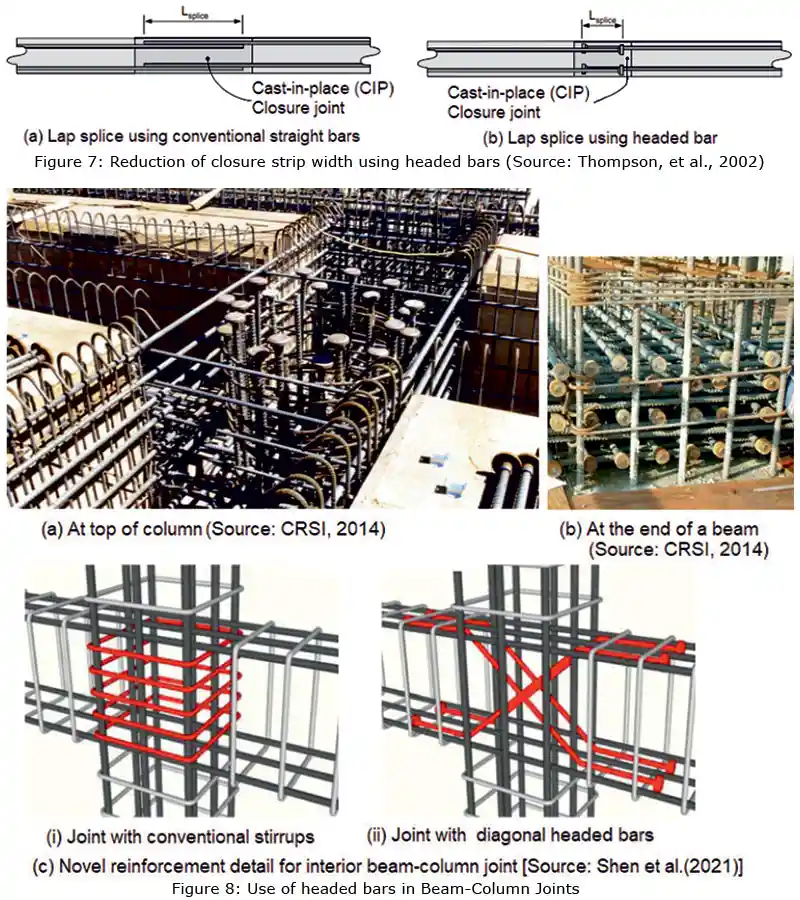
- Headed bars can potentially simplify the design and construction of complex bridge details such as closure strips, in which reduced splice lengths can be used to reduce the width of the closure gap (Fig. 7). Similarly, over lapping headed bars could be used instead of lapping to reduce the rebar length and at the same time reducing congestion.
- Where the main longitudinal bars are terminated, the development length to be provided for a straight or bent bar may be difficult to achieve (especially in beam-column joints). Similarly, there may be situations where the bent bars will result in rebar congestion. In such situations, the headed bars may provide a better solution. The beam-column joints with headed bars are shown in Fig.8. Shen et al. (2021) tested four numbers of 2/3-scale RC interior beam-column joint (BCJ) specimens using the novel reinforcement detail, as shown in Fig. 8(c) and found that this detail is able to relocate the plastic hinges away from beam-column joint interfaces. They were also able to improve the loading capacity, energy dissipation capacity, stiffness, and bonding condition of beam reinforcements within the cores of BCJs. Fig. 9 shows the shear walls and boundary columns at Rancho Mirage, California, USA, where headed bars have been used as end anchors in column-wall connection.
- In seismic zones, it is required to bend the transverse shear reinforcement in columns to 135o bends instead of the normal 90o bends, which may pose difficulties for workmen. In such situations, the use of headed bars will result in ease of construction [see Fig. 10(a)]. In thick slabs or rafts, the shear reinforcements in the form of headed bars could be simply dropped from the top and tied to the top layer of longitudinal reinforcement. The two common types are the single-headed studs welded to a continuous base rail and the double-headed studs crimped into a steel channel, as shown in Fig. 10(b). The base rail is used to position the studs at the required spacing. The shear stud rail system is sometimes referred as SSR in drawings. Experiments have shown that higher shear stress in concrete can be allowed in slabs and beams when headed bars are used as shear reinforcement, as there will not be any appreciable slip, compared to that of standard hooks and bends. Tables 22.6.6.1 and 22.6.6.3 of ACI 318-19 and Canadian code CSA A-23:2000 allow a 50 % increase in shear stress in concrete, when headed bars are used (Ghali and Dilger 1998, Ghali and Youakim, 2005, Subramanian, 2013). In addition, the ACI 318-19 allows the spacing between the studs to be ≤ 0.75d compared to 0.5d for stirrups. These differences in design rules permit lesser amount of shear reinforcement or thinner slab or beam when headed studs are used. The use of studs also has the advantage of saving labour costs due to the simplified installation of headed studs. IS 456: 2000 does not contain provisions for design using headed studs as shear reinforcement.
- In thin flat slabs, to prevent punching, headed studs are often used as punching reinforcement (See Fig. 10 and 11). Provisions for the design of flat slabs with stud-shear reinforcements were introduced in the 2005 version of the ACI code. IS 456 does not have such provisions till now. As per ACI 318-19, using headed studs to resist punching shear in slabs requires specifying shank diameter, spacing, and the height of the studs. More information on methods of design and worked out design examples are available in ACI-ASCE committee 421(1999), Dilger and Ghali (1981), Elgabry and Ghali (1990) and Ghali and Hammill (1992).
- T-headed bars can be used as main tie reinforcement in corbels, as shown in Fig.12. Yang et al. (2010) conducted tests on HSC corbels and found that T-headed bars as main tie reinforcement showed more improved load carrying capacity, stiffness, ductility, and crack control than the companion corbel specimen that had the main tie reinforcement welded to transverse bars.
 Figure 9: Use as end anchors in column-wall connection (Source: www.dextragroup.com)Figure 10: Use of headed bars as shear and punching shear reinforcement
Summary And Conclusions
Rebar congestion can result in labour intensive site fabrication and lead to reduction in performance of concrete sections. The use of headed bars in such situations, help to reduce rebar congestion, facilitating better concrete consolidation and making easy the rebar fabrication and handling at site, compared to the traditional bent bar anchorages. Thus, the use of headed rebars offers time and cost advantages, in addition to improvements in the quality of concrete. Headed bars with rectangular, round, or elliptical heads are available. Headed bar reinforcement is usually formed by friction welding of plates, forging an upset bearing surface at the end of a reinforcing bar, or forging threads into the end of the bar, which are then used to attach the plate. Most manufacturers of headed bars produce products with two sizes of heads - 4Ab and 9Ab. In the case of heads with 4Ab size, the anchorage is provided through a combination of bond and bearing. Whereas, the 9Ab head size may provide the required anchorage through bearing, and hence may not require any development length.
Figure 11: Headed studs as punching reinforcement-Typical arrangement (Adapted from ACI 318:19)Strut-and-tie models can be used to determine the anchorage length; the node and strut dimensions play a critical role in defining the anchorage length. A minimum anchorage length of 6 to 8db is often specified. The headed bar should comply with the provisions of ASTM A970. ACI 318:19 provides an equation to determine the development length of headed bars, with modification factors to take into account reinforcement coating, parallel tie reinforcement, side cover and confinement, and concrete strength. Grooved-headed and ribbed-headed bars may exhibit superior cyclic load resistance as compared to plain-headed bars. Headed bars can be used advantageously in a variety of applications, including beam-column joints, knee joints, pile caps, column-roof slab connections, anchor cantilever beams, dapped end beams, corbels, transverse shear reinforcements, and shear wall cross ties.
References
Figure 12: Use of Headed bars in Corbels (source: Yang et al., 2010)ACI 421.1 R-20 Guide to Shear Reinforcement for Slabs, American Concrete Institute, Farmington Hills, Michigan, 32 pp.
Alrasyid, H., Yoganata, Y.S., Suluch, M. and Iranata, D.(2017) “Headed Reinforcement in Concrete Structure: State of The Art”, 3rd International Conference on Construction and Building Engineering, AIP Conference Proceedings 1903,020015. https://doi.org/10.1063/1.5011495
ASTM A970/A970M-18, “Standard Specification for Headed Steel Bars for Concrete Reinforcement,” West Conshohocken, PA, 2018, 10 pp.
Bashandy, T.R. (1996) Application of Headed Bars in Concrete Members, Ph.D. thesis, The University of Texas at Austin.
Berner, D.E., Gerwick, B.C., and Hoff, G.C. (1991) “T-Headed Stirrup Bars,” Concrete International, ACI, Vol. 13, No. 5, pp.
Berner, D.E. and Hoff, G.C. (1994) “Headed Reinforcement in Disturbed Strain Regions of Concrete Members,” Concrete International, Vol. 16, No. 1, Jan.
Chourasia, A., Singhal, S., Parashar, J., Chourasia, A. (2023) “Reinforced concrete and beam-columns anchored with headed bars subjected to reversed cyclic loading: Experimental and numerical investigation”, Structural Concrete, pp.1-15. https://doi.org/10.1002/suco.202100468
Chun S-C., Lee, S-H., Kang, T.H.-K, Oh, B., and Wallace, J.W. (2007) “Mechanical anchorage in exterior beam-column joints subjected to cyclic loading”, ACI Structural Journal, Vol. 104, No. 1, pp. 102–112.
CRSI (2014), “Frequently Asked Questions (FAQ) About Headed Reinforcing Bars”, CRSI Technical Note ETN-M-3-14, Concrete Reinforcing Steel Institute, Schaumburg, Illinois, 8 pp.
DeVries, R.A. (1996) Anchorage of Headed Reinforcement in Concrete. Ph.D. thesis, The University of Texas at Austin.
Devries, R.A., Jirsa, J.O., and Bashandy, T. (1999) “Anchorage Capacity in Concrete of Headed Reinforcement with Shallow Embedments” ACI Structural Journal, Vol. 96, No. 5, pp. 728-737.
Dilger, W. H., and A. Ghali (1981) “Shear Reinforcement for Concrete Slabs”, Journal of the Structural Div., ASCE, Vol. 107, ST 12, Dec., pp. 2403 -2420.
Eligehausen, R., Mallée, R., and Silva, J. (2006) Anchorage in Concrete Construction, Ernst & Sohn, Berlin, Germany, May, 380 p.
Elgabry, A.E., and A. Ghali, Design of stud-shear reinforcement for slabs, ACI Structural Journal, Vol. 87, No. 3, May-June 1990, pp. 350-361.
Ghali, A., and W.H. Dilger (1998) “Anchoring with double headed studs”, Concrete International, ACI, Vol. 20, No. 11, Nov., pp.21-24.
Ghali, A., and N. Hammill (1992), Effectiveness of shear reinforcement in slabs, Concrete International, ACI, Vol. 14, No. 2, Feb., pp. 60-65.
Ghali A., and S.A. Youakim (2005) “Headed studs in concrete: state of the art”, ACI Structural Journal, Vol. 102, No. 5, Sept.-Oct., pp. 657–667.
Goodman, R. (2022) “Use of Headed Bars in Reinforced Concrete Design”, NBM & CW, July,
Kang, T.H.-K, Ha, S.-S. and Choi D.-U. (2010) “Bar pullout tests and seismic tests of small-headed bars in beam-column joints”, ACI Structural Journal, Vol. 107, No. 1, pp. 32–42.
Lequesne, R.D., O’Reilly, M., Darwin, D., Lepage, A., Al-Sabawy, A., Guillen, E., and Spradling, D. (2018) Use of Headed Bars as Shear Reinforcement, SM Report No.126, The University of Kansas Center for Research, Inc., Lawrence, Kansas, 265 pp.
Marchetto, F.(2015) Use of Headed Reinforcement Bars in Construction, Ph.D. Thesis, Department Of Continuum Mechanics and Theory of Structures, School Of Civil Engineering, Technical University Of Madrid, 355 pp. https://oa.upm.es/36378/1/FRANCESCO_MARCHETTO.pdf
McMackin P.J., Slutter R.G., and Fisher J.W. (1973) “Headed steel anchor under combined loading”, Engineering Journal, AISC, Vol. 10, 2nd Quarter, pp. 43–52.
Mokhtar, A.S., Ghali, A., and Dilger, W.H. (1985), “Stud Shear Reinforcement for Flat Concrete Plates,” Journal of the American Concrete Institute, Proc., Vol. 82, No. 5, Sept.-Oct., pp. 676-683.
Shao, Y.; Darwin, D.; O’Reilly, M.; Lequesne, R. D.; Ghimire, K.; and Hano, M. (2016), Anchorage of Conventional and High-Strength Headed Reinforcing Bars, SM Report No. 117, University of Kansas Center for Research, Lawrence, KS, 234 pp. https://kuscholarworks.ku.edu/ handle/1808/21738
Shen, Li, B., Chen, Y.-T., and Tizani, W. (2021) “Seismic Performance Of RC Interior Beam-Column Joints With Novel Reinforcement Detail”, Engineering Structures, Vol. 227, 111408, 13 pp.
Sim, H.-J., and Chun, S.-C. (2022) “Side-Face Blowout Failure Of Headed Bars In High-Strength Concrete”, ACI Structural Journal, Vol. 119, No. 5, Sept., pp. 3-16.
Stoker, J.R., Boulware, R.L., Crozier, W.F., and Swirsky, R.A. (1974) “Anchorage Devices for Large Diameter Reinforcing Bars,” Report No. CA-DOT-TL-6626-1-73-30, California Department of Transportation, Sacramento, California.
Subramanian, N. (2013) Design of Reinforced Concrete Structures, Oxford University Press, New Delhi, 880 pp.
Thompson, M.K. (2002) The Anchorage Behavior of Headed Reinforcement in CCT Nodes and Lap Splices, PhD Thesis, The University of Texas at Austin.
Thompson, M.K., Jirsa, O.J., and Breen, J.E. and Klingner, R.E. (2002) Anchorage Behavior of Headed Reinforcement: Literature Review, Research report FHWA/TX-0-1855-1, Center For Transportation Research, Bureau of Engineering Research, The University of Texas at Austin, 102 pp.
Thompson, M.K., Jirsa, O.J., and Breen, J.E. (2006) “CCT nodes anchored by headed bars- Part 2: capacity of nodes”, ACI Structural Journal, Vol. 103, No. 1, pp. 65-73.
Thompson, M.K., Jirsa, O.J., and Breen, J.E. (2006) “Behavior and Capacity of Headed Reinforcement”, ACI Structural Journal, Vol.103, No. 4, July-Aug., pp.522-530.
Thompson, M. K., Ledesma, A., Jirsa, O.J., and Breen, J.E. (2006) “Lap splices anchored by headed bars”, ACI Structural Journal, Vol. 103, No. 2, Mar.-Apr. 2006, pp. 271-279.
Yang, J.M., Min, K.H., Shin, H.O., and Y.S. Yoon (2010) “The use of T-headed bars in high-strength concrete members”, Conf. on Fracture Mechanics of Concrete and Concrete Structures-High Performance, Fiber Reinforced Concrete, Special Loadings and Structural Applications, May 23-28, B. H. Oh, et al. (eds.), Korea Concrete Institute, pp.1328-1334
Wright, J.L. and McCabe, S.L. (1997) The development length and anchorage behavior of headed reinforcing bars, SM Report 44, University of Kansas Center for Research, Lawrence, Kansas.
About the Author
International Concrete Construction Technology, Jan - Feb 2023