
Quality Control Measures Prior to Pouring of Concrete for Deep Foundations
Parthasarathy C R, Nandhagopal A R, Srinivas N, and Soumik Ghosal, at Sarathy Geotech & Engineering Services, Bengaluru. present the methods to understand the processes involved during installation of bored cast-in-situ piles using two of the latest equipment from Pile Dynamics Inc. (PDI).
The installation of bored cast-in-situ piles generally involves a four-step process starting with boring at pile location, lowering of the prepared steel reinforcement, flushing of the borehole, and finally concreting. During this process, an understanding of the borehole with regards to its cross-section along the depth, verticality, and the sediments or sludge at the bottom of the borehole is necessary. Casting concrete without understanding these points will cause issues such as overconsumption of concrete, soft toe, unintended rake of the pile, etc, which, in turn, will affect the design strength and cost of casting of the pile. This affects the project costings and design on a major scale when the number of deep foundations adopted are high. Therefore, it is important to understand the profile of the pile borehole and bottom cleanliness.
 Drilled shafts or bored cast-in-situ piles are the most commonly used deep foundations in the Indian subcontinent for all major infrastructure and commercial projects. The process involves drilling a borehole, lowering down of a reinforcement cage prepared according to the design requirements, flushing the hole for any bottom sediments and finally, concreting the borehole. The present technology allows bored cast-in-piles of larger diameters of 1.2 to 1.8m till a depth more than 60m. In small scale projects, the Direct Mud Circulation (DMC) method is adopted and in major projects, the drilling is performed with rotary rigs.
There have been several cases of underperformance of bored cast-in-situ piles. One of the major reasons can be identified as the improper stabilisation of the borehole sides and bottom during different stages of boring operations (Anirudhan, 2009). Soil collapse during the boring operation is a common problem, despite bore hole stabilization with bentonite slurry, particularly in a loose cohesion less saturated soil (Gandhi S R, 2015). Such soil collapse on the borehole walls causes greater consumption of concrete while having an irregularly bulged shape of the pile, and an increase in the cost of installation as well.
IS 14593 - 2008 recommends not to consider any frictional resistance from the overburden soil for rock-socketed piles. Since there may not be much settlement at the tip of the pile resting on the rock, mobilization of friction in overburden layers with little relative movement between the pile and soil is not warranted. As a result, it is preferable to get all the resistance from the socketed portion and hence, it is particularly essential that the bottom of the borehole for a rock-socketed pile be clear of any sediments to mobilise the end-bearing resistance.
Toe debris is the common defection of bored piles. When the thickness of toe debris piles is large, the safety of pile foundation will be threatened (AASHTO, 2017). Due to presence of excess sediments, when the load reaches a certain value, sudden and large subsidence can be observed (Wang et al., 2020). FHWA NHI-18-024 – Drilled shaft manual recommends only an allowable limit of average sediment deposit which is less than 0.5’’ (12.7mm) thickness.
In this paper, the efficiency of the latest state-of-the-art PDI equipment which can identify both borehole cross-sectional profile and bottom sediment thickness have been presented using a case study.
The SQUID a device used for measuring the extent of the debris layer at the base of a drilled shaft. The device is equipped with three penetrometers and three retractable displacement plates which are used to record force and displacements simultaneously. The test procedure consists of attaching the SQUID device to the Kelly bar and lowering it into the drilled hole. Once the device is located at the bottom of the hole, the weight of the Kelly-Bar will transfer sufficient force to allow the penetrometers to penetrate through the debris layer and into the bearing layer. Simultaneously, the displacement plates retract measuring the corresponding displacements. Based on established thresholds, the debris layer is determined from the force and displacement plots. The resulting force versus displacement information provide a quantitative measure of the debris thickness at the foundation base.
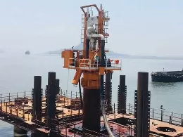
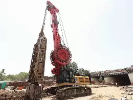
 Figure 1: Site Photographs – Conduct of SHAPE and SQUID
 Figure 2: SHAPE Results – Sample profile views
Considering the consistency of a debris material, it is reasonably assumed that it will have strength properties similar to a soft to medium clay with an unconfined compressive strength ranging between 12 kPa and 200 kPa, and a unit weight ranging between 16kN/m3 and 19kN/m3. With these strength parameters and applying the general bearing capacity theory proposed by Terzaghi (1943) for circular foundations, equation (1), the penetration force for a flat tip with a cross section area of 10 cm2 was determined to be between 0.089 kN and 0.708kN.
Figure 2: SHAPE Results – Sample profile views
Considering the consistency of a debris material, it is reasonably assumed that it will have strength properties similar to a soft to medium clay with an unconfined compressive strength ranging between 12 kPa and 200 kPa, and a unit weight ranging between 16kN/m3 and 19kN/m3. With these strength parameters and applying the general bearing capacity theory proposed by Terzaghi (1943) for circular foundations, equation (1), the penetration force for a flat tip with a cross section area of 10 cm2 was determined to be between 0.089 kN and 0.708kN.
qult=1.3Su Nc
Where the qult is the ultimate bearing capacity of a circular base, Su is the undrained shear strength of the material, and Nc is the bearing capacity factor.
The SQUID Tablet and its related software has the capability of setting force thresholds to determine the debris thickness from the Force-Displacement plots. Once the threshold options are enabled, the difference between the displacement corresponding to 0.709kN (Penetrometer Threshold) and the displacement corresponding to 0.09kN (Debris Threshold) represents the debris thickness.

The system measured both the thickness of soft material or debris that may be covering the bearing strata, providing a force and displacement in numerical and graphical form. As shown in Table 3, a total of 11 runs were conducted in that only five were analysed and presented in Table 4 and some sample results are shown in Figure 3.
 Figure 3: SQUID Results – Sample Run data
The installation of bored cast-in-situ piles generally involves a four-step process starting with boring at pile location, lowering of the prepared steel reinforcement, flushing of the borehole, and finally concreting. During this process, an understanding of the borehole with regards to its cross-section along the depth, verticality, and the sediments or sludge at the bottom of the borehole is necessary. Casting concrete without understanding these points will cause issues such as overconsumption of concrete, soft toe, unintended rake of the pile, etc, which, in turn, will affect the design strength and cost of casting of the pile. This affects the project costings and design on a major scale when the number of deep foundations adopted are high. Therefore, it is important to understand the profile of the pile borehole and bottom cleanliness.
Introduction
There have been several cases of underperformance of bored cast-in-situ piles. One of the major reasons can be identified as the improper stabilisation of the borehole sides and bottom during different stages of boring operations (Anirudhan, 2009). Soil collapse during the boring operation is a common problem, despite bore hole stabilization with bentonite slurry, particularly in a loose cohesion less saturated soil (Gandhi S R, 2015). Such soil collapse on the borehole walls causes greater consumption of concrete while having an irregularly bulged shape of the pile, and an increase in the cost of installation as well.
IS 14593 - 2008 recommends not to consider any frictional resistance from the overburden soil for rock-socketed piles. Since there may not be much settlement at the tip of the pile resting on the rock, mobilization of friction in overburden layers with little relative movement between the pile and soil is not warranted. As a result, it is preferable to get all the resistance from the socketed portion and hence, it is particularly essential that the bottom of the borehole for a rock-socketed pile be clear of any sediments to mobilise the end-bearing resistance.
Toe debris is the common defection of bored piles. When the thickness of toe debris piles is large, the safety of pile foundation will be threatened (AASHTO, 2017). Due to presence of excess sediments, when the load reaches a certain value, sudden and large subsidence can be observed (Wang et al., 2020). FHWA NHI-18-024 – Drilled shaft manual recommends only an allowable limit of average sediment deposit which is less than 0.5’’ (12.7mm) thickness.
In this paper, the efficiency of the latest state-of-the-art PDI equipment which can identify both borehole cross-sectional profile and bottom sediment thickness have been presented using a case study.
Problem statement
A pile of diameter 1000mm is to be cast and the pile borehole has already been bored. The depth of the shaft is 21.2m and casing is installed to a depth of 4.5m. The profile of the borehole and the bottom cleanliness is to be confirmed prior to the pouring of the concrete to ensure good quality of pile and in turn idealising the design and cost as per the construction plan. The state-of-the-art equipment known as Shaft Area Profile Evaluator (SHAPE) and Shaft Quantitative Inspection Device (SQUID) have been used to achieve the same.Equipment used
Shaft Area Profile Evaluator (SHAPE) consists of the following:- The SHAPE Body is cylindrical with a diameter of 355 mm (14 in), height of 914 mm (36 in), and a total weight of 45.36 kg (100 lbs.). The SHAPE Body is powered by an external 12V battery that provides 4 to 6 hours of continuous usage. It has 8 receivers and 8 transmitters, which are placed in a ring, facing outwards, separated in 45º increments. An electrical signal is applied to the transducer, causing the piezoelectric sensing element located inside the transducer to abruptly change shape. This results in an ultrasonic pressure wave. The wave travels out perpendicularly from the transducer’s surface into the slurry until it reaches the shaft wall. Then, the wave is reflected toward the transducer. The distance is calculated by the measured wave speed (calibrated by two sensors embedded at a known distance) in slurry and the time required for the wave to travel to the excavation wall and back.
- The SQUID Body has an octagonal shape with a maximum diagonal length of 647 mm, height of 635 mm, and a total weight of 188 kg.
- Three penetrometers and three retractable contact plates are part of the SQUID System which are used to record force and displacements simultaneously. All contact plates are designed to be retracted at a pressure equivalent to 0.10 kN, and measuring displacements up to 160 mm. The penetrometers are designed to be used with conical or flat tips with an average cross-sectional area of 10 cm2. The resistance to penetration is measured by strain gages arranged in a full Wheatstone bridge, with the capability of recording up to 100 MPa of pressure.
Methodology
The Shaft Area Profile Evaluator (SHAPE) an electronic device was used to measure sidewall distances for wet cast drilled foundations. The system generates ultrasonic pulses transmitted through the drilling medium and measures reflection time from the sidewall. The system calculates the distance from each sensor to the sidewall based on a measured wave speed in the drilling medium. The SHAPE allows for fast deployment and evaluation of collected data to minimize the time between drilling completion and concrete placement. The deployment can be through the winch or the Kelly of the piling rig.The SQUID a device used for measuring the extent of the debris layer at the base of a drilled shaft. The device is equipped with three penetrometers and three retractable displacement plates which are used to record force and displacements simultaneously. The test procedure consists of attaching the SQUID device to the Kelly bar and lowering it into the drilled hole. Once the device is located at the bottom of the hole, the weight of the Kelly-Bar will transfer sufficient force to allow the penetrometers to penetrate through the debris layer and into the bearing layer. Simultaneously, the displacement plates retract measuring the corresponding displacements. Based on established thresholds, the debris layer is determined from the force and displacement plots. The resulting force versus displacement information provide a quantitative measure of the debris thickness at the foundation base.
Test procedure
SHAPE test procedure was conducted summarized as follows:- To facilitate the specified testing, the access to the shaft location and a work area surrounding the shaft that was free of debris was provided in accordance with all pertinent safety requirements and applicable safety standards.
- The SHAPE device was pin connected to the Kelly bar using a 10” adapter provided by the SHAPE equipment supplier for the trail.
- After the pin-connection and prior to positioning over the open excavation for testing, the verticality of the SHAPE Unit was checked and confirmed.
- The SHAPE device was connected to the SHAPE tablet using an ethernet cable.
- Once the “ready” indicator is activated (usually a flashing blue LED light), the SHAPE device was disconnected from the tablet and a watertight cap was securely placed on the Ethernet connector.
- The SHAPE device was then centred over the shaft excavation and lowered down the drilled hole for verticality and drilled shaft shape determination.
- A SHAPE test run is defined as a full descending and ascending transit of the SHAPE device. The SHAPE test was performed at a descending and ascending rate of approximately one foot per second (300 mm/sec).
- After the ascending transit and once at the surface, the SHAPE device was reconnected to the SHAPE tablet using an ethernet cable to transfer the SHAPE device collected data to the SHAPE tablet.
- At the end of run, the data was checked and saved prior to terminating the test.
Figure 1: Site Photographs – Conduct of SHAPE and SQUID- The SQUID device was also pin connected to the Kelly bar using a 10” adapter provided as done for the SHAPE.
- The verticality of the SQUID unit and the connections and signal transmission to the tablet were confirmed.
- Signal transmission was checked by manually lifting each displacement plate and observing the increasing displacement on the SQUID Tablet.
- SQUID Unit was moved over the open shaft excavation and lowered without rotation until the unit is approximately 0.6 m above the shaft base.
- The test was proceeded by slowly lowering the Kelly bar without rotation until the entire weight of the Kelly bar is transferred to, and is resting on, the SQUID Unit.
- Penetrometer force and plate displacement measurements was continuously acquired, displayed, and stored on the SQUID Tablet during the test process.
- For first few trails no force was registered with all penetrometers reached 152mm. Cleaning was adapted & further runs was conducted.
- For last five trails, the three penetrometers have registered the maximum force & penetrometer travel of 152 mm is reached for all the penetrometers.
- Test run was terminated as its registered maximum force for all three penetrometers.
- At the end of run, the data was checked and saved prior to terminating the test.
Pile Details
The details of the pile are as listed in Table 1.Table 1: Information on pile details |
||
| S.No | Description | Information |
| 1 | Diameter of Shaft | 1000mm |
| 2 | Length of Shaft | 21.2m |
| 3 | Casing Length | 4.5m |
| 4 | Testing Length (SHAPE) | 18m |
| 5 | Date of Boring | 19/08/2023 |
| 6 | Date of Testing | 19/08/2023 |
Test results - SHAPE
The SHAPE system generates ultrasonic pulses transmitted through the drilling medium and measures reflection time from the sidewall. The system calculates the distance from each sensor to the sidewall based on a measured wave speed in the drilling medium. The results of the trial performed on this pile are shown in Table 2. Some sample profiles of the pile are also presented in Figure 2.Table 2: SHAPE Results Summary |
||
| Test Method | Using Kelly bar | |
| Tested Length, m | 18.0 | |
| Offset, m | 0.10 | |
| Verticality, % | 0.55 | |
| Eccentricity | X-axis | Y-axis |
| 0.10 | 0.01 | |
Test results and interpretation – SQUID
Figure 2: SHAPE Results – Sample profile viewsqult=1.3Su Nc
Where the qult is the ultimate bearing capacity of a circular base, Su is the undrained shear strength of the material, and Nc is the bearing capacity factor.
The SQUID Tablet and its related software has the capability of setting force thresholds to determine the debris thickness from the Force-Displacement plots. Once the threshold options are enabled, the difference between the displacement corresponding to 0.709kN (Penetrometer Threshold) and the displacement corresponding to 0.09kN (Debris Threshold) represents the debris thickness.
Table 3: SQUID Test Summary |
|
No of runs conducted |
11 |
| No of runs analysed | 5 |
| Directions of runs analysed | 5 |
| Depth of testing, m | 21.2 |
The system measured both the thickness of soft material or debris that may be covering the bearing strata, providing a force and displacement in numerical and graphical form. As shown in Table 3, a total of 11 runs were conducted in that only five were analysed and presented in Table 4 and some sample results are shown in Figure 3.
Figure 3: SQUID Results – Sample Run dataConclusions
► Based on the data acquired for the depth of 18.0 m from top the casing using the SHAPE equipment, it can be concluded that:- Eccentricity observed maximum of 0.10m and 0.01 for this pile from the axis.
- Observed maximum offset of 0.10 m for the pile.
- The eccentricity was about 0.55% which is within the permissible limit for infrastructure projects.
- During the initial few runs of SQUID testing, contaminations of the base is more than 150mm. Subsequently after cleaning bucket operations, further SQUID testing was conducted.
- Maximum and Minimum debris thickness was 11.6 mm and 0.2mm respectively. This is less than average of 12.7mm meeting the requirement for concreting (FHWA NHI-18-024, Drilled Shafts Manual) and normal industry practice.
- When paired with post-installation quality checks such as Pile Integrity Testing (PIT), Cross-Hole Sonic Logging (CSL), Thermal Integrity Profiling (TIP), and High-Strain Dynamic Pile Load Test (HSDPLT) the process of constructions can aim to be as close to being flawless as possible.
- It is recommended that awareness of these existing quality measures be raised and mandatorily implemented in all projects involving deep foundation constructions.
References
- AASHTO LRFD for Bridge Design Specifications. 8th Edition, American Association of State Highway and Transportation Officials, Washington, 2017.
- Anirudhan I V., (2009), Construction of Bored Cast-in-situ Piles using Rotary Drilling Procedure—A Case Study, IGC 2009, Guntur, India.
- Bureau of Indian Standards (IS): 14593 (2008) Design and construction of bored cast-in situ piles founded on rocks: guidelines, New Delhi.
- FHWA NHI-18-024 - Drilled Shafts: Construction Procedures and Design Methods, GEC No. 10 (2018), Geotechnical Engineering Circulars, US Department of Transportation, Federal Highway Administration, Washington, D.C., www.fhwa.dot.gov.
- Gandhi S R., (2015), Observations on Pile Design and Constructions Practices in India, Indian Geotechnical Journal 46 (1) 1 -15, DOI 10.1007/s40098-015-0171-5.
- Tie Hang Wang, Liang Zhang, Yan Zhou Hao, Xin Jin, (2020), Side Friction of Rock-Socketed Piles Involving Thick Sediment, Advances in Civil Engineering, vol. 2020, Article ID 8882698, 13 pages, https://doi.org/10.1155/2020/8882698.
NBM&CW SEPTEMBER 2023